


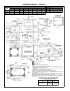
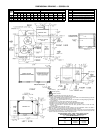
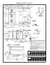
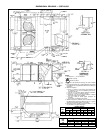
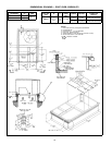
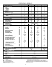
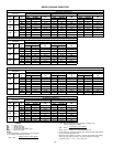
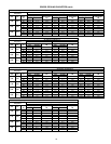
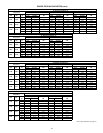

SPECIFICATIONS — 558D036-072
UNIT SIZE 036 048 060 072
NOMINAL CAPACITY (tons) 3456
OPERATING WEIGHT (lb)
Unit
Al/Al* 365 375 395 470
Economizer
Durablade 34 34 34 34
Parablade 42 42 42 42
Roof Curb† 115 115 115 115
COMPRESSOR Hermetic
Quantity
No. Cylinders (per circuit)
1
2
1
2
1
2
1
2
Oil (oz) 50 50 50 54
REFRIGERANT TYPE R-22
Operating Charge (lb-oz)
Circuit 1 3-6 4-11 5-13 7-10
Circuit 2 ————
CONDENSER COIL Enhanced Copper Tubes, Aluminum Lanced Fins
Rows...Fins/in. 1...17 1...17 1...17 2...17
Total Face Area (sq ft) 7.36 11.39 13.19 10.42
CONDENSER FAN Propeller Type
Nominal Cfm 4100 4100 4100 4100
Quantity...Diameter (in.) 1...22.0 1...22.0 1...22.0 1...22.0
Motor Hp...Rpm
1
⁄
4
...1100
1
⁄
4
...1100
1
⁄
4
...1100
1
⁄
4
...1100
Watts Input (Total) 325 325 325 325
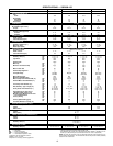
EVAPORATOR COIL Enhanced Copper Tubes, Aluminum Double-Wavy Fins
Expansion Device Acutrol™ Feed Device
Rows...Fins/in. 2...15 2...15 3...15 4...15
Total Face Area (sq ft) 4.17 5.5 5.5 5.5
EVAPORATOR FAN Centrifugal Type
Quantity...Size (in.) Std 1...10 x 10 1...10 x 10 1...11 x 10 1...10 x 10
Alt 1...10 x 10 1...10 x 10 1...10 x 10 —
Type Drive Std Direct Direct Direct Belt
Alt Belt Belt Belt —
Nominal Cfm 1200 1600 2000 2400
Motor Hp Std ————
Alt ————
Maximum Continuous Bhp Std .34 .75 1.20 2.40
Alt 1.00 1.00 1.80 —
Motor Frame Size Std 48 48 48 56
Alt 48 48 48 —
Nominal Rpm High/Low Std 860/800 1075/970 1075/970 —
Alt ————
Fan Rpm Range Std — — — 1070-1460
Alt 760-1000 835-1185 900-1300 —
Motor Bearing Type Ball Ball Ball Ball
Maximum Allowable Rpm 2100 2100 2100 2100
Motor Pulley Pitch Diameter A/B (in.) Std — — — 2.8/3.8
Alt 1.9/2.9 1.9/2.9 2.4/3.4 —
Nominal Motor Shaft Diameter (in.) Std
1
⁄
2
1
⁄
2
1
⁄
2
5
⁄
8
Alt
1
⁄
2
1
⁄
2
1
⁄
2
—
Fan Pulley Pitch Diameter (in.) Std ———4.5
Alt 4.5 4.0 4.5 —
Belt, Quantity...Type...Length (in.) Std — — — 1...A...40
Alt 1...A...34 1...A...34 1...A...39 —
Pulley Center Line Distance (in.) Std — — — 14.7-15.5
Alt 10.0-12.4 10.0-12.4 14.7-15.5 —
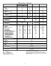
Speed Change per Full Turn of Std ———80
Movable Pulley Flange (rpm) Alt 48 70 80 —
Movable Pulley Maximum Full Turns Std ———5
From Closed Position Alt 555—
Factory Setting Std ———3
Alt 333—
Factory Speed Setting (rpm) Std — — — 1225
Alt 856 975 1060 —
Fan Shaft Diameter at Pulley (in.)
1
⁄
2
1
⁄
2
1
⁄
2
1
⁄
2
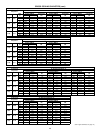
HIGH-PRESSURE SWITCH (psig)**
Standard Compressor Internal Relief 450±50 500±50
Cutout 428 428
Reset (Auto.) 320 320
LOW-PRESSURE SWITCH (psig)**
Cutout 7±3
Reset (Auto.) 22±7
FREEZE PROTECTION THERMOSTAT (F)**
Opens 30±5
Closes 45±5
OUTDOOR-AIR INLET SCREENS Cleanable
Quantity...Size (in.) 1...20 x 24 x 1
RETURN-AIR FILTERS Throwaway
Quantity...Size (in.) 2...16 x 25 x 2
LEGEND
Al — Aluminum
Bhp — Brake Horsepower
FIOP — Factory-Installed Option
TXV — Thermostatic Expansion Valve
*Evaporator coil fins/condenser coil fins.
†Weight of 14-in. roof curb.
**Requires the accessory controls upgrade kit.
††Circuit 1 consists of lower portion of both the condenser and evaporator coils, and
Circuit 2 consists of the upper portion of both coils.
The 559F300 units require 2-in. industrial-grade filters capable of handling face ve-
locities up to 625 ft/min (such as American Air Filter no. 5700 or equivalent).
NOTE: The 036-150 units have a loss-of-charge/low-pressure switch (accessory or op-
tion) located in the liquidline. The 180-300 units have a low-pressure switch (standard)
located on the suction side.
14