


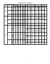
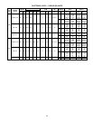
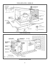
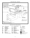
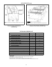
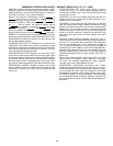
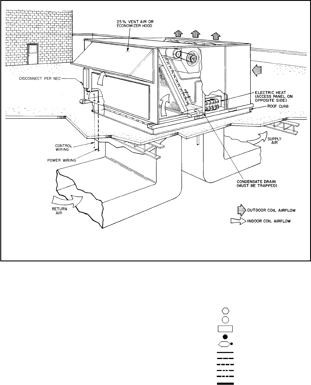
TYPICAL INSTALLATION — 559F180-300
NEC — National Electrical Code
NOTES:
1. Illustration shown is a general guide only and is not intended to
include all details for any specific installation.
2. Installation must comply with all applicable codes.
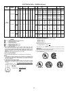
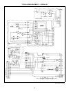
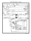
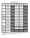
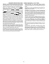
LEGEND FOR TYPICAL WIRING SCHEMATICS
AHA — Adjustable Heat Anticipator
BRK W/AT — Breaks With Amp Turns
C—Contactor, Compressor
CB — Circuit Breaker
CC — Cooling Compensator
CH — Crankcase Heater
CLO — Compressor Lockout
CLS — Compressor Lockout Switch
COMP — Compressor Motor
CT — Current Transformer
DM — Damper Motor
DU — Dummy Terminal
EC — Enthalpy Control
EQUIP — Equipment
FL — Fuse Link
FPT — Freeze Protection Thermostat
FU — Fuse
GND — Ground
HC — Heater Contactor
HPS — High-Pressure Switch
HTR — Heater
IFC — Indoor (Evaporator) Fan Contactor
IFCB — Indoor (Evaporator) Fan Circuit Breaker
IFM — Indoor (Evaporator) Fan Motor
IFR — Indoor (Evaporator) Fan Relay
IP — Internal Protector
L—Light
LOR — Lockout Relay
LPS — Low-Pressure Switch
LS — Limit Switch
MAT — Mixed-Air Thermostat
NC — Normally Closed
NEUT — Neutral
NO — Normally Open
OAT — Outdoor-Air Thermostat
OFC — Outdoor (Condenser) Fan Contactor
OFM — Outdoor (Condenser) Fan Motor
OP — Overcurrent Protector
PL — Plug Assembly
PRI — Primary
QT — Quadruple Terminal
SW — Switch
SW1 — Switch, Fully Open
SW2 — Switch, Fully Closed
SW3 — Switch, Minimum Vent Position
SW4 — Switch, Maximum Vent Position
TB — Terminal Block
TC — Thermostat Cooling
TH — Thermostat Heating
TRAN — Transformer
Terminal (Marked)
Terminal (Unmarked)
Terminal Block
Splice
Splice (Marked)
Factory Wiring
Field Control Wiring
Field Power Wiring
Accessory Wiring or Optional Wiring
Accessory
To indicate common potential only,
not to represent wiring
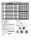
59