


INSTALLATION DIRECTIVE
7
V08 ENT M75
-
M11
-
M12
MAY 2006
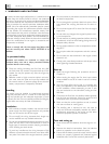
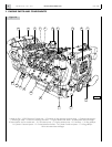
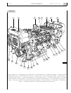
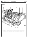
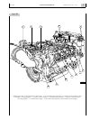
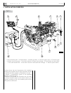
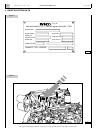
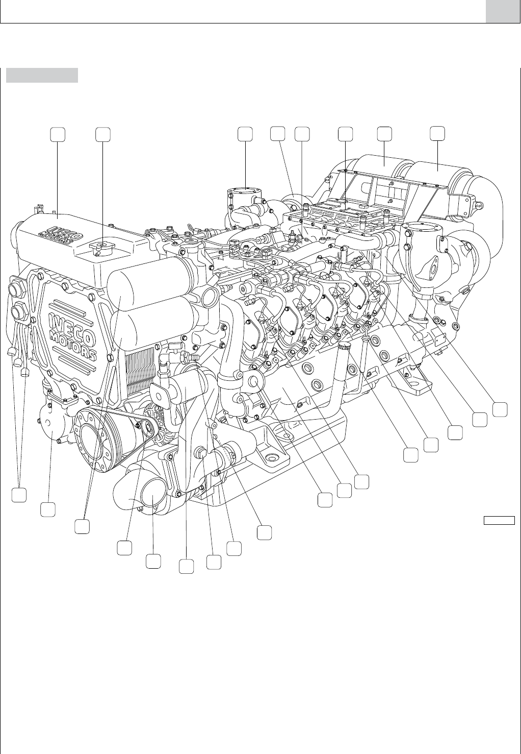
Figure 1B
05_008_V
9
15
13
10
11
16
20
7
1
2
7
3 6
12
8
14
5
4
17
19
23
22
21
24
18
1. Engine coolant tank - 2. Pressurization cap for coolant tank - 3. Exhaust gas outlet - 4. Cooled turbo-charger - 5. Common rail high
pressure injection pump - 6. EDC Electronic Central Unit - 7. Intake air filter - 8. Air-sea water heat exchanger - 9. Lifting padeyes -
10. Cylinder 8 electro-injector - 11. Lubricating oil dipstick - 12. Lubricating oil refill cap - 13. Cylinder 5 electro-injector - 14. Cooled
exhaust manifold - 15. Lifting padeyes - 16. Location of the low pressure fuel transfer pump - 17. Tap and fitting for lubricating oil
transfer - 18. Sacrificial anode - 19. Lubrication oil transfer electrical pump - 20. Sea water intake - 21. Alternator - 22. Lubricating
oil filters - 23. Engine coolant pump - 24. Electrical equipment wiring connectors.