


INSTALLATION DIRECTIVEMAY 2006
11
V08 ENT M75
-
M11
-
M12
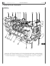
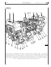
4. GENERAL INSTALLATION CRITERIA
Accessibility
The engine must be located in such a way as to allow filling
and draining engine liquids when doing servicing operations.
Moreover, the relay box and the diagnostic push-button
present on it must be accessible, also when underway.
Anchoring
If anchoring is accomplished by interposing shock mounts,
they must be able to support the engine’s mass and the lon-
gitudinal thrust exerted by the propeller shaft in motion.
If rigid mounting is adopted, particular care must be given to
support alignment and co-planarity.
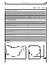
Information on dimensions and fastening values are provided
in the “Installation Diagram”.
Combustion and ventilation air
Compliance with prescriptions on the quantity of air
required for combustion and ventilation assures a regular
operation of the engine even in adverse conditions and it
enables to deliver its maximum rated power (1).
Sea water line
It must be provided with an intake capable of preventing
the entry of foreign bodies into the suction pipes. Between
the intake and the pump, it is best to interpose a gate to be
closed in emergencies or for extended idle periods and a
filter to stop the smaller impurities; it is also recommended
to install a suitably dimensioned and easily replaced zinc
anode.
The engine sea water line was provided by the manufacturer
with protection anodes to be replaced periodically.
The rubber hoses positioned along the pipeline shall be suffi-
ciently rigid not to create choked areas caused by crushing (1).
Engine pre-heating
If the engine usage profile requires immediate delivery of
power at the highest rpm’s, it is recommended to install an
auxiliary pre-heater on the closed cooling loop.
Exhaust gas outlet
The exhaust gas outlet conduits shall be compliant with the
guidelines contained in the IVECO MOTORS publication
“Guide to the installation of marine engines”; it also provides
indications to compute the dimensions of the exhaust pipe-
lines, which is the Yard’s responsibility.
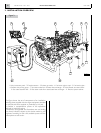
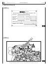
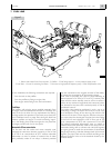
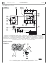
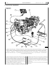
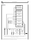
Electric - electronic equipment
Provide a suitable arrangement of the relay box, and of the
optional electronic unit referring to the dimensions and posi-
tion of the wire harnesses and the relative connectors.
Both units must be anchored in such a way as to dampen the
vibrations and stresses undergone by the hull while under-
way and/or induced by the engine’s operation.
NOTE: Information about optional equipment are described
in the Chapter 21.
(1) The EDC engine electronic control is programmed to
reduce maximum deliverable power if the operating
parameters measured by the sensors show that criti-
cal conditions have been reached, and if exceeded the
engine could be damaged.