INSTALLATION DIRECTIVE MAY 2006
36
V08 ENT M75
-
M11
-
M12
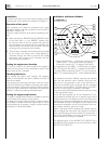
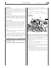
CAUTION
In order to enable the proper working of the sensor to
detect water in fuel, the pre-filter support needs to be
electrically connected to the negative battery terminal.
In the engine models which use parts with insulated poles
it is necessary to electrically insulate the prefilter support
from the boat mass and then connect the support with the
negative battery terminal.
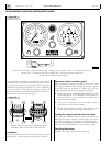
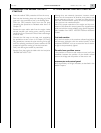
Neutral gear sensor
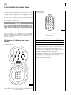
CAUTION
When neutral gear sensor is installed remember to con-
nect it to GN connector.
In installation without sensor, do not remove the cap of
the GN connector to avoid compromising start engine
function.
Sensor to detect water in fuel
Fuel resistivity sensor, integrated with the control and ampli-
fication electronic circuit, providing the signal for the indica-
torof the presence of water in the fuel.
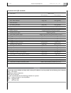
Operating voltage from 12 to 24 V
Condition in the absence of water open circuit
Closed condition resistance of the liquid
≤ 1 MΩ
Operating temperature from -20 to +80 °C
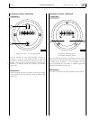
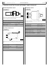
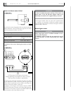
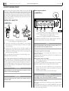
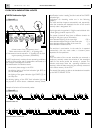
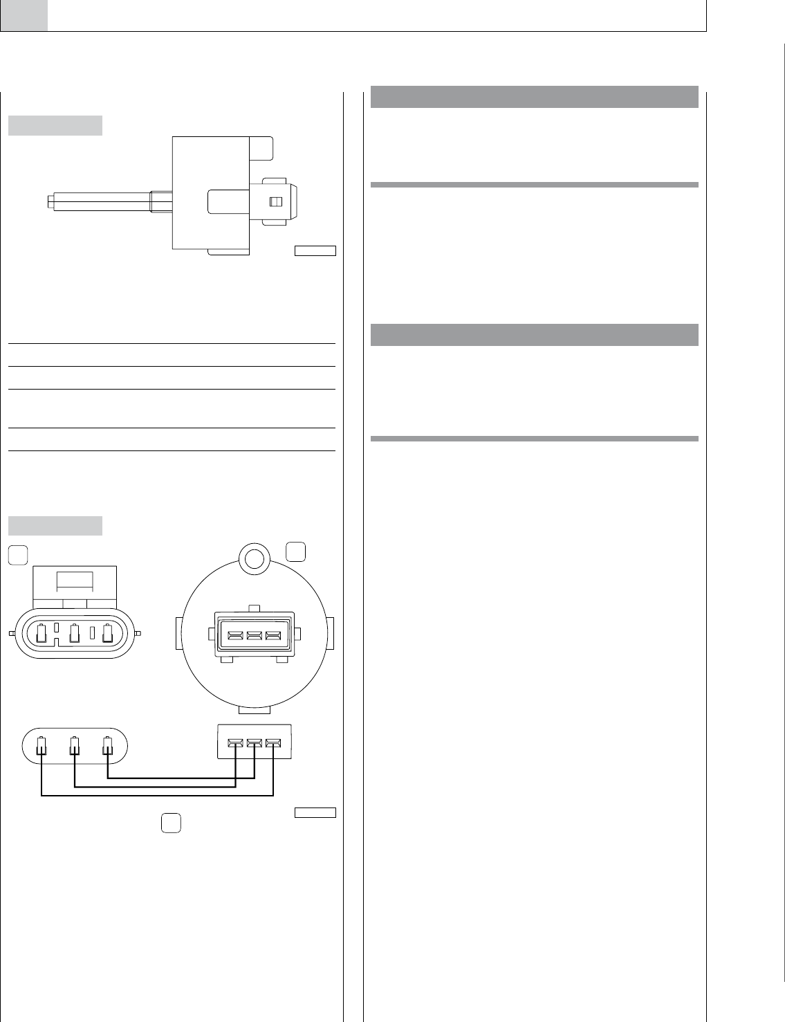
Connections of the sensor detecting the presence of water
in fuel
1. M Connector of the engine wire harness -
2. Sensor detecting the presence of water in the fuel -
3.Wiring harness (outfitter’s responsibility).
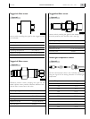
The three pole connection between the sensor for detect-
ing the presence of water in the fuel and the engine wire
harness must be produced by the outfitter according to the
position of the fuel prefilter in the boat.
Connection to the engine wire harness requires a METRI-
PACK150 three-pole connector with three male terminals;
connection to the sensor requires a JUNIOR TIMER three-
pole connector with three female terminals.
Figure 44
04_031_C
Figure 45
1 2 3
1 2 3
1 2 3
1 2 3
3
1
2
05_017_V


