


INSTALLATION DIRECTIVE MAY 2006
32
V08 ENT M75
-
M11
-
M12
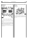
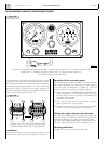
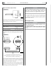
12. CUSTOMIZED INSTRUMENT PANEL
Using only the components of the panel that are not wired
to allow the panel customization, they will have to be wired
using the 10 metre long wire harness, set up at one end for
coupling to the JB connector and at the opposite end with
conductors with free terminals with identifying numbering
on each wire. The conductors will have to be connected to
the individual components as indicated in the electrical and
wiring diagrams in Chapter 20.
CAUTION
To assure the functionality of the safeties pertaining to the
engine start/stop commands from the instrument panel or
engine room, it is mandatory to wire the key switch strictly
as shown in the electrical diagrams in Chapter 20.
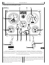
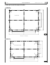
The wiring details of the indications and alarms module
alone are provided below; indications for IVECO MOTORS
indicator instruments are shown in the related wiring dia-
grams in Chapter 20.
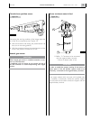
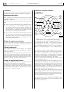
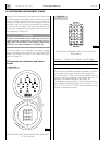
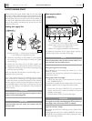
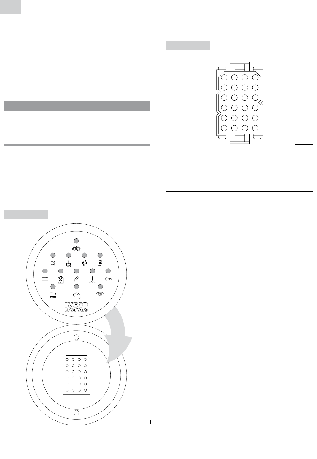
JD Connector for indications and alarms
module
VIEW FROM THE SIDE INTEGRATED IN THE REAR PART
OF THE MODULE
Figure 34
VIEW FROM THE TERMINAL SIDE OF THE COUPLING
SIDE WIRING
connector
TRIDENT / ITT CANNON part TST 24PA00
terminal
female part 192990-0050
lid
rear part TST24AH0
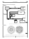
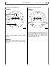
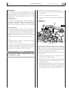
JD connects the indications and alarms module to the elec-
trical system of the engine (sensors, power supply, etc.).
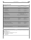
The terminal part of the wire harness, supplied with the
module, must be completed using female terminals, as
described in the electrical diagram of Chapter 20.
For standard-equipped engines, to have the essential indica-
tions available, the following ways must be wired: 1, 3, 7, 8,
9, 10, 11, 13, 14, 15, 16, 17, 18, 19 with the female terminals
supplied as standard equipment.
Figure 35
13
9
5
1
14 15
16
10 11 12
6
2
4
7 8
3
21 22 23 24
17 18 19 20
04_241_N
123
4
568 7
10
912 11
1314
16
15
171820 19
212224 23
05_034_C