


INSTALLATION DIRECTIVE MAY 2006
20
V08 ENT M75
-
M11
-
M12
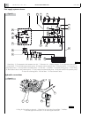
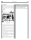
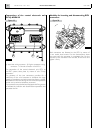
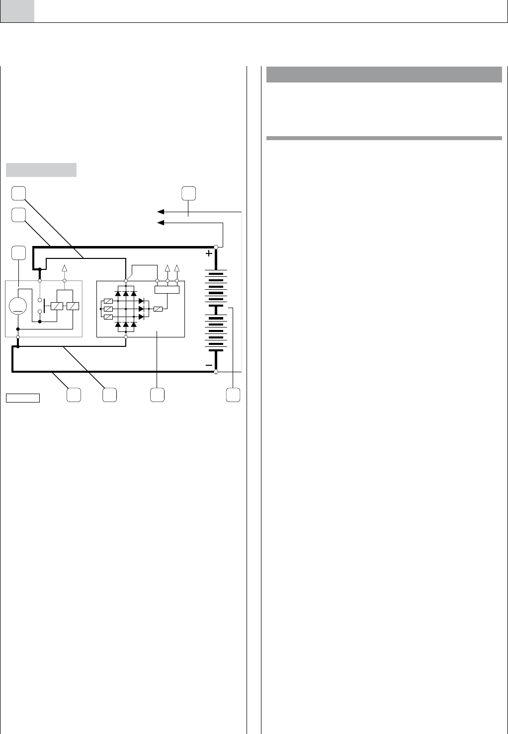
Power supply line
The power network must be carried out in order to avoid
using both the structure of engine and the structure of the
hull (if this is metallic). For this purpose the electrical starter
motor and the alternator required for this equipment are
characterized by the presence of the terminals for electrical
connections both with the positive and with the negative
pole of the battery.
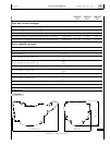
1. Alternator - 2. Electrical starter motor - 3. Battery -
4. Engine wire harness.
The power supply line, to be built by the yard, comprises:
o A. Connection between the negative pole of the battery
and the terminal “–B” of the electric starter motor
realized with a conductor having a cross section of at
least 95 mm
2
;
o B. Connection between the positive pole of the batte-
ry and the terminal “30” of the electrical starter motor
realized with a conductor having a cross section of at
least 50 mm
2
;
o C. Connection between the “30” terminal of the alter-
nator to the positive “+B” terminal of the electric starter
motor, to close the power supply and recharge circuit
of the battery realized with a conductor having a cross
section of at least 50 mm
2
.
o D. Connection between the “−B” terminal of the alter-
nator to the positive “−B” terminal of the electric starter
motor, to close the power supply and recharge circuit
of the battery realized with a conductor having a cross
section of at least 50 mm
2
.
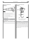
The connection of the electric equipment of the engine to
the battery has to be carried out via the two eyed terminals,
“+B” and “–B”, present on the wiring harness.
Figure 13
-
)'3"
,
n"
Equipment power supply
05_113_C
B
C 4
1
2
A 3D
CAUTION
If magneto-thermal protecting breakers are installed on
the wiring lines of the engine control system, they must
not be used to stop the engine and in any case they must
be activated only a few seconds after shut-off.