


INSTALLATION DIRECTIVE MAY 2006
24
V08 ENT M75
-
M11
-
M12
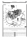
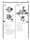
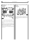
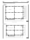
Modality for inserting and disconnecting ECU
connectors
Both connectors are fastened to the ECU by means of
4 mm socket head screws. For the disconnection: loose
the screw until the connector is completely free. For the
insertion: fit the connector into the seat, fit the screw and
tighten it firmly.
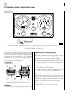
Figure 20
05_048_V
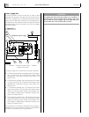
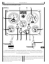
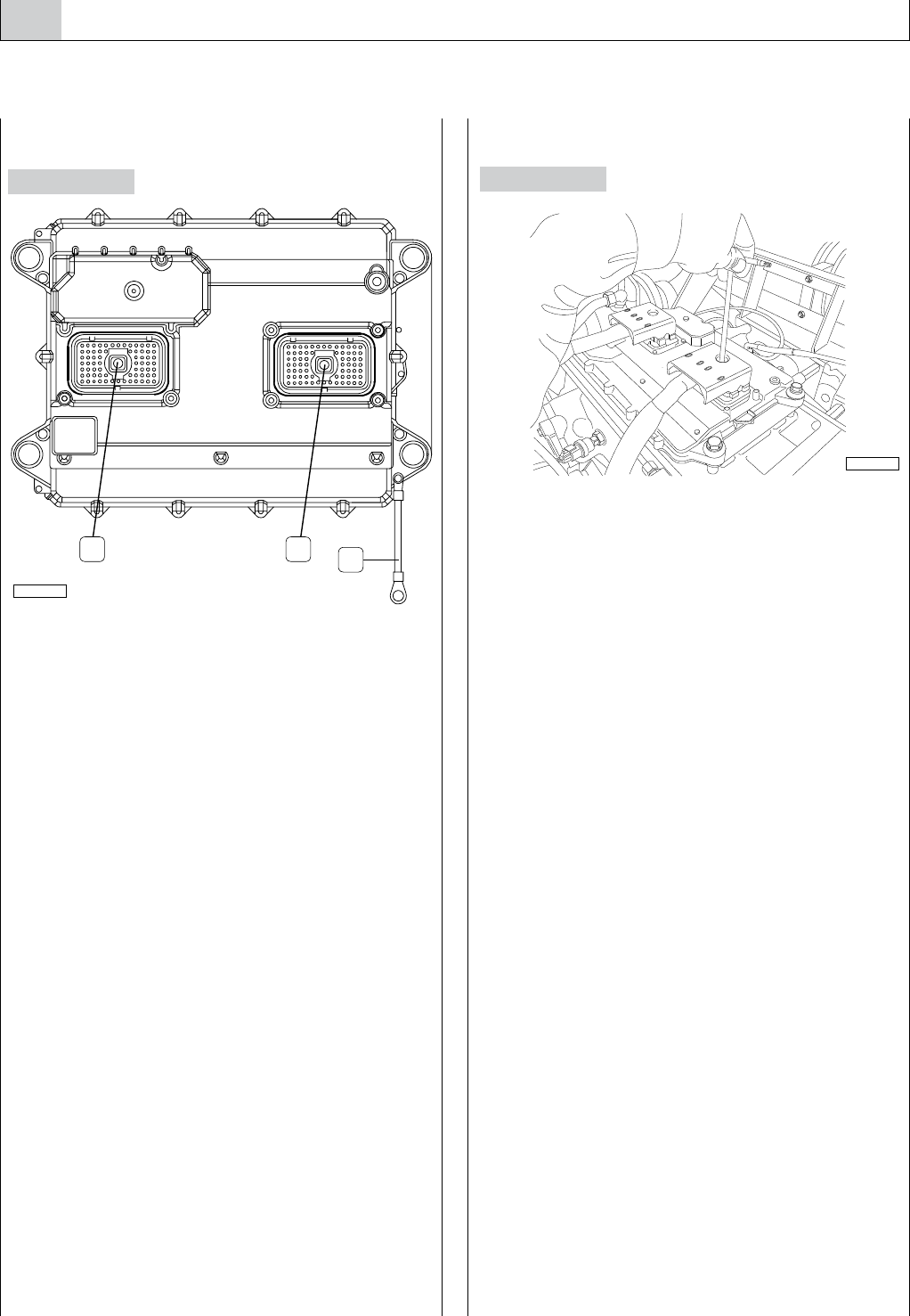
Connections of the central electronic unit
(ECU) ADEM III
J1. Vessel side wiring connector - J2. Engine component wiring
connector - A. Ground connection of the ECU.
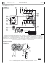
The connection of the central electronic unit, ECU, to
the EDC system, takes place by means of two 70-way
connectors.
The presence of the two connectors provides for a
subdivision of the wire harnesses to distribute the large
quantity of conductors and at the same time favour a quicker
identification of the lines during the service check operations
carried out by technical assistance personnel.
The connectors are polarized and equipped with fixing screws
to facilitate the insertion and disconnection operations and
guarantee the link.
Figure 19
J1 J2
A
05_010_V