


INSTALLATION DIRECTIVE MAY 2006
28
V08 ENT M75
-
M11
-
M12
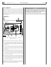
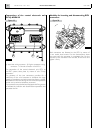
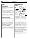
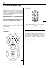
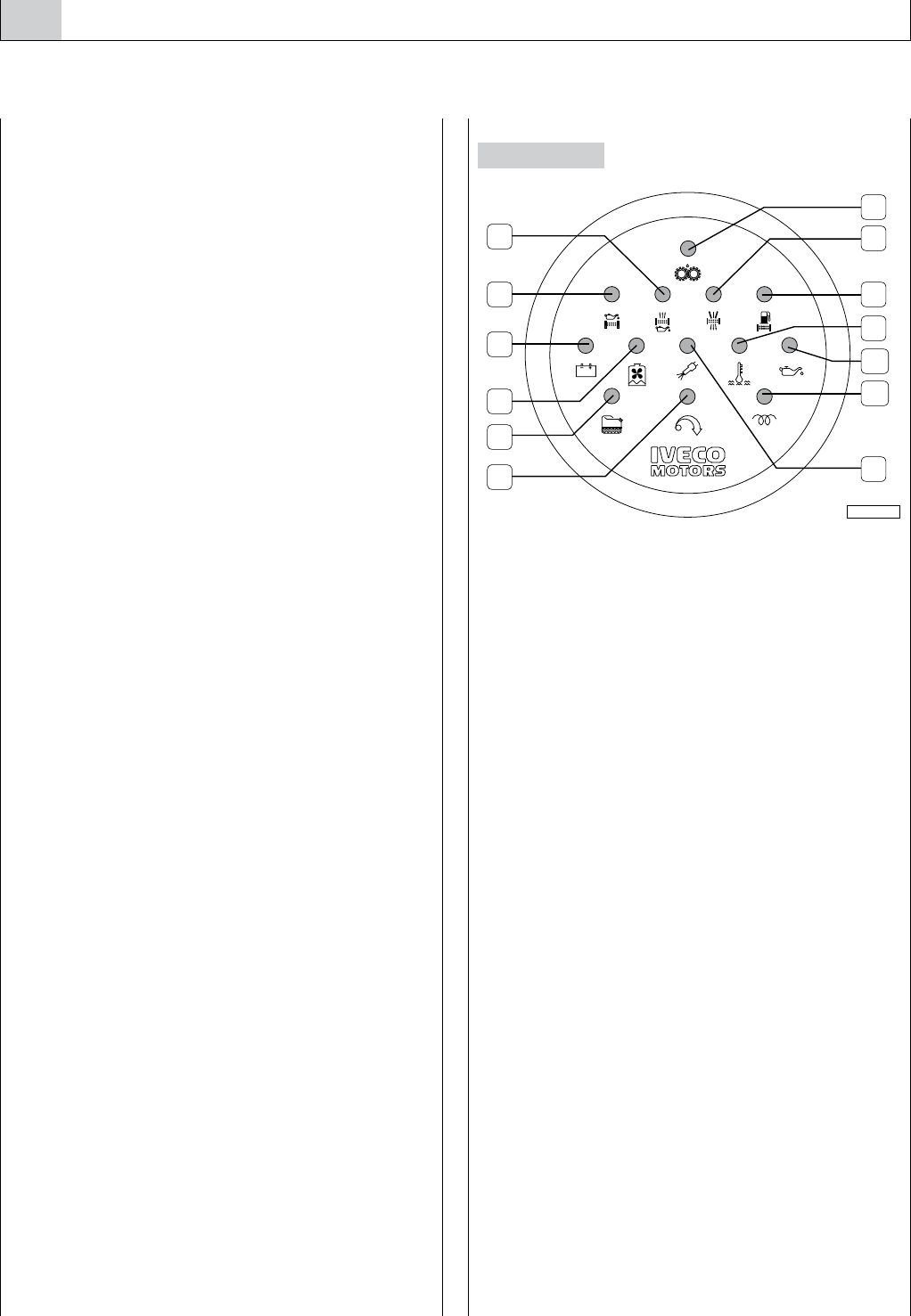
Indications and Alarms Module
1. Engine overspeed (SSV) - 2. Presence of water in the fuel
prefilter (SAC) - 3. Low engine coolant level (SBLA) -
4. Alternator anomaly (SS) - 5. Clogged oil filter (SIFO)-
6. Clogged blow-by filter (SIFB) - 7. Pre-lubrication in progress
(SP) - 8. Clogged air filter (SIFA) - 9. Clogged fuel filter (SIFC) -
10. High coolant temperature (SATA) - 11. Low oil pressure
(SBPO) - 12. Pre/post heating (SCP) - 13. EDC Malfunction (EDC).
The Indications and Alarm Module comprises the indicator
lights and the electronic alarm interface, timing and stor-
age circuit. It is programmed in such a way that when it is
powered, all indicator lights are lighted, with the exception
of those for “pre-lubrication”, “pre-post heating” and “EDC”
failure and a sound signal is emitted by the buzzer.
The buzzer may be silenced before the end of the test, acting
on the appropriate control.
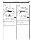
During the starting phase and for the subsequent 15 sec-
onds, needed to stabilize the low oil pressure signal, all the
module’s functions are inhibited; once this time interval has
elapsed, every alarm state detected by the sensors will cause
the associated indicator to be lighted and the buzzer to be
powered; the exceptions are the “pre-lubrication” and “pre-
post heating” indicators, given only visually.
When a new alarm state is detected, the indicator light will
flash to highlight the occurrence with respect to any others
which may be ongoing at the time. When the sound alarm is
shut off, the light indicator will remain lighted and the alarm
will be stored until the engine is stopped.
The standard set-up of the V08 ENT M75, V08 ENT M11
and V08 ENT M12 provides for use of the indicators: SBLA,
SIFA, SIFC, SIFO, EDC, SS.
2
4
8
13
1
3
5
6
9
12
10
11
7
04_234_N
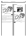
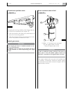
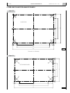
Installation
In order to drill holes on the area where the panel is to be
mounted, refer to the dimensions indicated in Chapter 11.
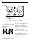
Operation of the panel
After completing the electrical connections and engine
preparation, perform the tests required for the first start, as
described in Chapter 18.
Verify the proper operation of the panel, proceeding as fol-
lows:
o Make sure that the “ENGINE ROOM / BRIDGE” switch
of the Relay Box is in the “BRIDGE” position, then
turn the key switch to the first position and verify that
the instruments are powered and the Indications and
Alarms Module runs the alarm test for about 5 seconds
according to the procedures set out below.
o Once the test is complete, only the indications prescribed
for the engine not running must remain lighted: e.g.
“alternator charge” and “low oil pressure”; the analog
instruments must provide values consistent with the
relevant physical parameters.
Testing the engine start function
Turn the key switch in the second position and release it
quickly; the start function is fully controlled by the ECU and
begins when the key is released.
Checking indications
After starting the engine, verify whether the operating
modes of the Indications and Alarms Module are similar to
those set out below.
Using appropriate measuring instruments, verify the consis-
tency of the indications provided by the analog instruments.
Verify the indication of the panel revolution counter, compar-
ing it with the one measured by a reference instrument; if the
indication is different, proceed as described below.
Testing the engine stop function
The engine is stopped and the panel is disabled by returning
the key switch to the resting or zero position.
The panel has an engine stop push-button whose function is
only enabled in versions where the engine stops as a result
of the excitation of an actuator, i.e. engine versions requiring
certification by Certification Bodies.
Figure 26