


INSTALLATION DIRECTIVE
17
V08 ENT M75
-
M11
-
M12
MAY 2006
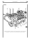
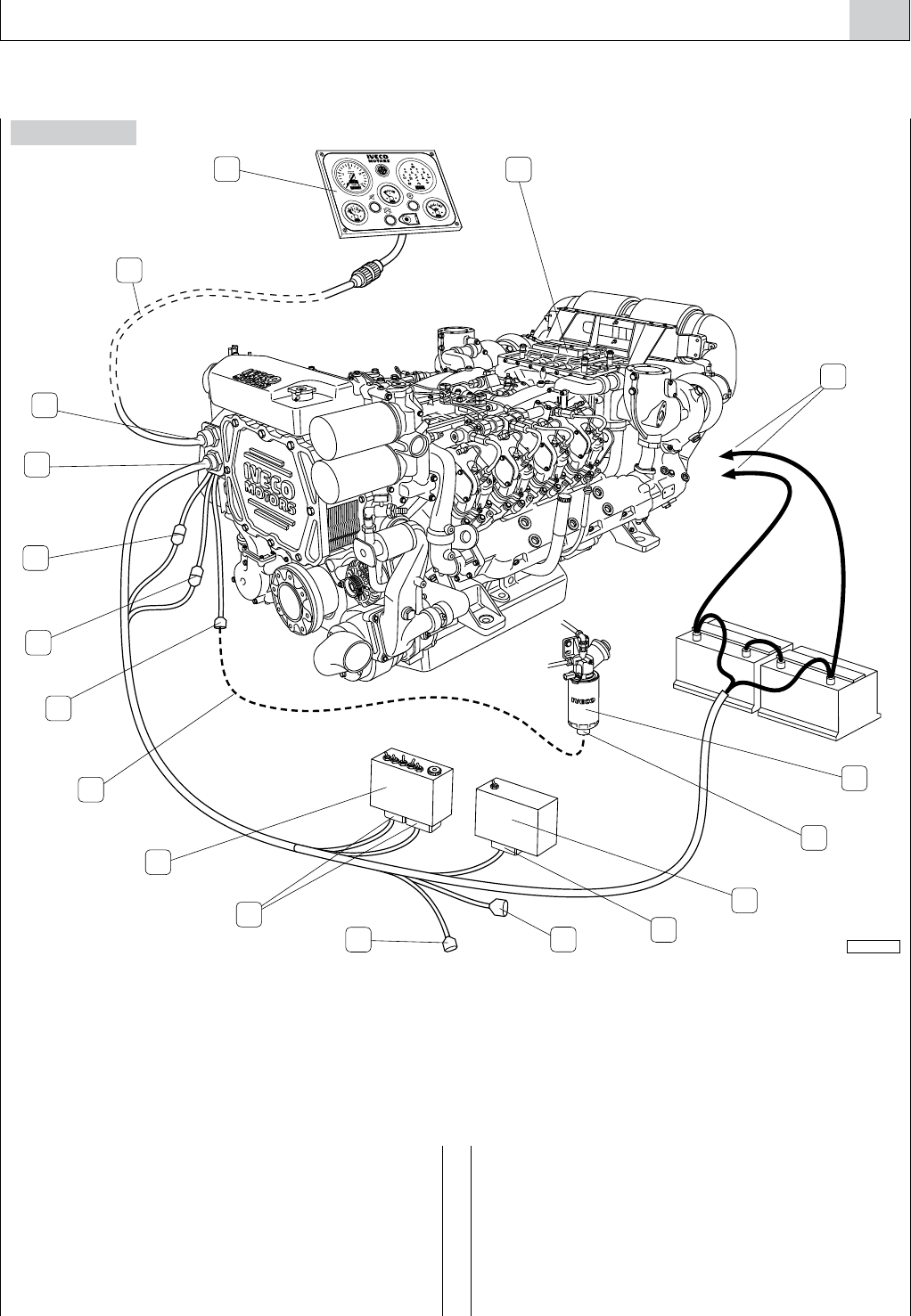
8. ELECTRICAL EQUIPMENT
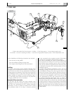
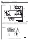
Figure 10
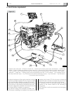
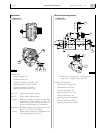
The electrical equipment of the engine comprises a series of
components provided separately from the engine to enable
an easy and diversified installation, according to the Yard’s
design choices. The need to make accessible, at sea or under-
way, the controls to the electrical components and to the
connector for diagnostics contained in the relay box may be
met through different installation arrangements.
Along with the coupling of all connectors provided in the
wire harnesses, completing the installation also requires the
connecting wire harness (12) for the sensor to detect the
presence of water in fuel (5), to complete the power line and
to connect the accumulator to the engine wire harness.
The connection of the J3 connector enables the electric
connection of the control module to the lubricating oil
pouring pump.
The JC connector is set for the connection to the emergency
stop button.
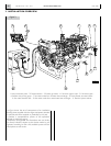
05_013_V
4
5
1
18
3
17
2
16
15
14
13
12
7
11
10
9
8
6
1. Indicator and control panel - 2. Electronic Central Unit - 3. Power line for electric starter motor and alternator - 4. Sedimenting
prefilter - 5. Sensor to detect the presence of water in the fuel - 6. Control unit of the lubrication oil transfer electrical pump -
7. JG Connector - 8. JG1 Connector for control unit of the lubrication oil electrical pump - 9. JC Connector - 10. JF1 and JF2
connectors - 11. Relay box - 12. Wiring harness to be manufactured by the yard - 13. M Connector - 14. J4 Connector for the
electrical pre-lubrication pump - 15. J3 Connector for the electrical lubricating oil pump - 16. JA Connection - 17. JB Connection -
18. Instrument panel wire harness.