


Chapter 5 Troubleshooting & Repair Series 220/221 Instruction Manual
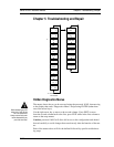
Electronics Assembly Replacement (All Meters)
The electronics boards are electrostatically sensitive. Wear a grounding
wrist strap and make sure to observe proper handling precautions re-
quired for static-sensitive components.
1. Turn off power to the unit.
Warning!
Before attempting any flow
meter repair, verify that the
line is not pressurized.
Always remove main power
before disassembling any
part of the mass flow meter.
2. Locate and loosen the small set screw which locks the larger
enclosure cover in place. Unscrew the cover to expose the
electronics stack.
3. Locate the sensor connector that comes up from the neck of
the flow meter and attaches to the circuit board. Use small
pliers to pull the connector off of the circuit board.
4. Locate and loosen the small set screw which locks the smaller enclo-
sure cover in place. Unscrew the cover to expose the field wiring
strip. Tag and remove the field wires.
5. Remove the screws that hold the black wiring label in place, remove
the label.
6. Locate the 4 Phillips head screws which are spaced at 90-degrees
around the terminal board. These screws hold the electronics stack in
the enclosure. Loosen these screws (Note: that these are captive
screws, they will stay inside the enclosure).
7. Carefully remove the electronics stack from the opposite side of the
enclosure. If the electronics stack will not come out, gently tap the
terminal strip with the screw driver handle. This will loosen the rub-
ber sealing gasket on the other side of the enclosure wall. Be careful
that the stack does not hang up on the loose sensor harnesses.
8. Repeat steps 1 through 6 in reverse order to install the new electron-
ics stack.
5-6 IM-22