


Chapter 2 Installation Series 220/221 Instruction Manual
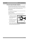
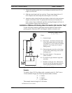
Installing Flow Meters with a Compression Connection*
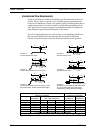
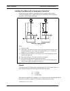
Use the following formula to determine insertion length for flow meters
(NPT and flanged) with a compression process connection. The installation
procedure is given on the next page.
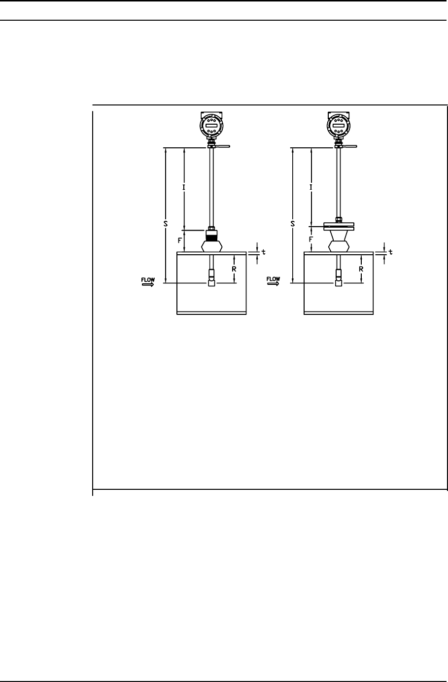
Insertion Length Formula
I = S – F – R – t
Where:
I = Insertion length.
S = Stem length – the distance from the center of the sensor head to the base of the
enclosure adapter (S = 29.47 inches for standard probes; S = 13.1 inches for
compact; S = 41.47 inches for 12-inch extended).
F = Distance from the raised face of the flange or top of NPT stem housing to the
outside of the pipe wall.
R = Pipe inside diameter ÷ 2 for pipes ten inches and smaller.
R = Five inches for pipe diameters larger than ten inches.
t = Thickness of the pipe wall. (Measure the disk cut-out from the tapping proce-
dure or check a piping handbook for thickness.)
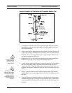
Figure 2-6. Insertion Calculation (Compression Type)
Example:
To install a Series 221 meter with a standard probe (S = 29.47 inches) into a 14
inch schedule 40 pipe, the following measurements are taken:
F = 3 inches
R = 5 inches
t = 0.438 inches
The insertion length for this example is 21.03 inches. Insert the stem through the fit-
ting until an insertion length of 21.03 inches is measured with a ruler.
*All dimensions are in inches
2-10 IM-22