


Series 220/221 Instruction Manual Chapter 2 Installation
Flow Meter Insertion
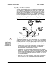
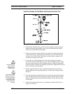
The sensor head must be properly positioned in the pipe. For this reason, it is
important that insertion length calculations are carefully followed. A sensor
probe inserted at the wrong depth in the pipe will result in inaccurate readings.
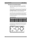
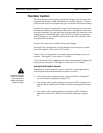
Insertion flow meters are applicable to pipes 2 inch and larger. For pipe sizes
ten inches and smaller, the centerline of the meter’s sensing head is located at
the pipe’s centerline. For pipe sizes larger than ten inches, the centerline of the
sensing head is located in the pipe’s cross section five inches from the inner
wall of the pipe; i.e., its “wetted” depth from the wall to the centerline of the
sensing head is five inches.
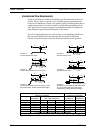
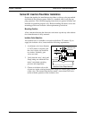
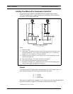
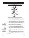
Insertion flow meters are available in three probe lengths:
Standard Probe configuration is used with most flow meter process connec-
tions. The length, S, of the stem is 29.47 inches.
Compact Probe configuration is used with compression fitting process con-
nections. The length, S, of the stem is 13.1 inches.
12-Inch Extended Probe configuration is used with exceptionally lengthy flow
meter process connections. The length, S, of the stem is 41.47 inches.
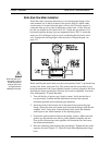
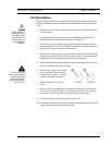
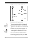
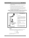
Use the Correct Insertion Formula
Warning!
An insertion tool must be
used for any installation
where a flow meter is
inserted under pressure
greater than 50 psig.
Depending on your flow meter’s process connection, use the applicable in-
sertion length formula and installation procedure as follows:
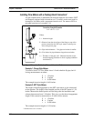
• Flow meters with a compression type connection (NPT or flanged) fol-
low the instructions beginning on page 2-10.
• Flow meters with a packing gland type connection (NPT or flanged) con-
figured with an insertion tool, follow the instructions beginning on page
2-12.
• Flow meters with a packing gland type connection (NPT or flanged)
without an insertion tool, follow the instructions beginning on page 2-
15.
IM-22 2-9