


Chapter 2 Installation Series 220/221 Instruction Manual
Series 221 Insertion Flow Meter Installation
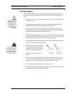
Prepare the pipeline for installation using either a cold tap or hot tap method
described on the following pages. Refer to a standard code for all pipe tap-
ping operations. The following tapping instructions are general in nature and
intended for guideline purposes only. Before installing the meter, review the
mounting position and isolation value requirements given below.
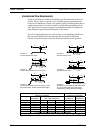
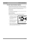
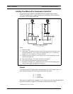
Mounting Position
Allow clearance between the electronics enclosure top and any other obstruc-
tion when the meter is fully retracted.
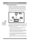
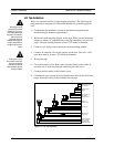
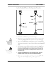
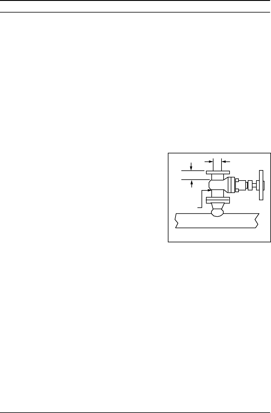
Isolation Valve Selection
An isolation valve is available as an option with Series 221 meters. If you
supply the isolation valve, it must meet the following requirements:
2-6 IM-22
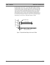
1. A minimum valve bore diameter
of 1.875 inches is required, and
the valve’s body size should be
two inches. Normally, gate
valves are used.
2. Verify that the valve’s body and
flange rating are within the flow
meter’s maximum operating
pressure and temperature.
3. Choose an isolation valve with
at least two inches existing between the flange face and the gate portion
of the valve. This ensures that the flow meter’s sensor head will not in-
terfere with the operation of the isolation valve.
1.875-inch min.
valve bore
2-inch min.
2-inch
valve size
Isolation Valve Requirements