


Series 220/221 Instruction Manual Chapter 2 Installation
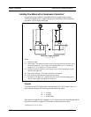
Insertion Procedure for Meters with a Compression Connection
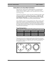
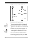
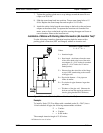
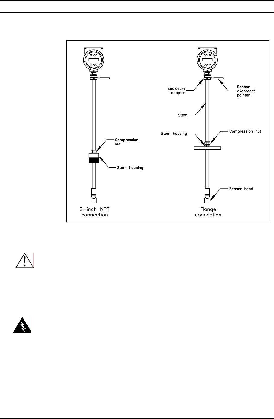
Figure 2-7. Flow Meter with Compression Type Fitting
1. Calculate the required sensor probe insertion length.
Caution!
The sensor alignment
pointer must point
downstream, in the
direction of flow.
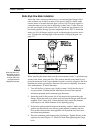
2. Fully retract the stem until the sensor head is touching the bottom of the
stem housing. Slightly tighten the compression nut to prevent slippage.
3. Bolt or screw the flow meter assembly into the process connection. Use
Teflon tape or pipe sealant to improve the seal and prevent seizing on NPT
styles.
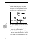
4. Hold the meter securely while loosening the compression fitting. Insert
the sensor into the pipe until the calculated insertion length, I, is meas-
ured between the base of the enclosure adapter and the top of the stem
housing, or to the raised face of the flanged version. Do not force the
stem into the pipe.
Warning!
To avoid serious injury,
DO NOT loosen the
compression fitting
under pressure.
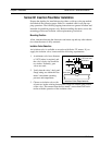
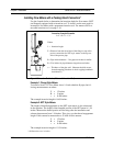
5. Align the sensor head using the sensor alignment pointer. Adjust the
alignment pointer parallel to the pipe and pointing downstream.
6. Tighten the compression fitting to lock the stem in position. When the
compression fitting is tightened, the position is permanent.
IM-22 2-11