


Chapter 2 Installation Series 220/221 Instruction Manual
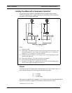
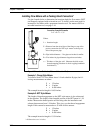
Insertion Procedure for Flow Meters with No Insertion Tool
(Packing Gland Connection)
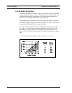
1. Calculate the required sensor probe insertion length.
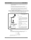
Warning!
The line must be
less than 50 psig
for installation.
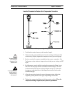
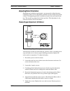
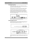
2. Fully retract the stem until the sensor head is touching the bottom of the
stem housing. Remove the two top stem clamp nuts and loosen two stem
clamp bolts. Slide the stem clamp away to expose the packing gland nuts.
Loosen the two packing gland nuts.
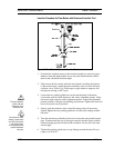
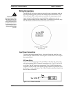
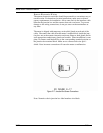
3. Align the sensor head using the sensor alignment pointer. Adjust the
alignment pointer parallel to the pipe and pointing downstream.
Caution!
The sensor alignment
pointer must point
downstream, in the
direction of flow.
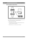
4. Insert the sensor head into the pipe until insertion length, I, is achieved.
Do not force the stem into the pipe.
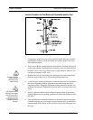
5. Tighten the packing gland nuts to stop leakage around the stem. Do not
torque over 20 ft-lbs.
6. Slide the stem clamp back into position. Torque stem clamp bolts to 15
ft-lbs. Replace the stem clamp nuts and torque to 10-15 ft-lbs.
2-16 IM-22