17
GUIDE LINE ADJUSTMENT
AFTER REAR VIEW CAMERA INSTALLATION
The guide lines on the screen need to be aligned with the image taken from the rear view camera (and
other reference items) so that the system is correctly matched to the vehicle.
There are seven reference items to align including,
(1) View-from-top angle alignment
(2) Center-line alignment
(3) View-from-top height alignment
(4) Left/right guide lines alignment
(5) Right guide line alignment
(6) 3 ft. guide line alignment
(7) 1.5 ft. guide line alignment
During the alignment process, the screen automatically changes to the view-from-top and all the
alignment parameters are automatically reflected in the digitally corrected rear view.
Preparation before performing alignment procedure
The following auxiliary items are required for alignment. Prepare them in advance.
1. Locate an area with parallel lines painted on a
tarmac or similar flat surface such as a parking lot.
2. Prepare markers to indicate the center line of the
vehicle.
3. Prepare two markers to indicate the width of the
vehicle.
4. Ruler to measure 1.5 ft. and 3 ft., and two markers.
• Cans or bottles make good markers.(Marking tape
for alignment is provided with this Rear View Back
up Camera System to indicate 1.5 ft. and 3 ft. guide
lines, and the width of the vehicle.)
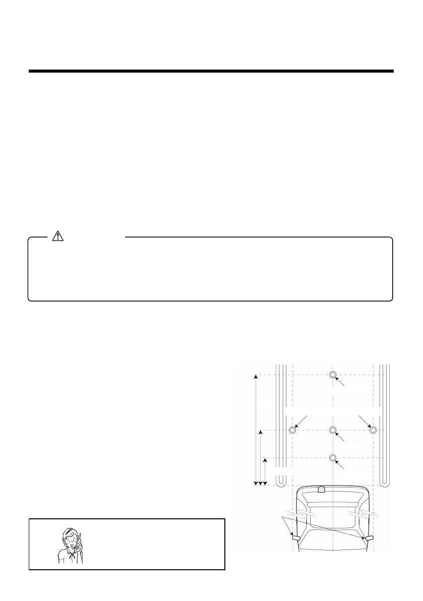
Park the vehicle parallel to the parking space lines and
place markers shown in the right figure:
• Install the Rear View Back up Camera system in a safe place away from other
vehicles and pedestrians. Set the emergency brake and block the wheels so that
the vehicle does not move while aligning the system. If the vehicle deviates and
the alignment is done incorrectly, it could result in an accident.
CAUTION
Center marker
Markers to indicate width of vehicle
3 ft. marke
r
1.5 ft. marke
r
Side Mirror
1.5 ft.
3 ft.
6 ft.
Need help? Call
1-800-421-5013


