


13
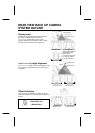
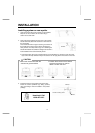
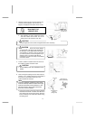
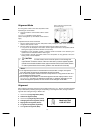
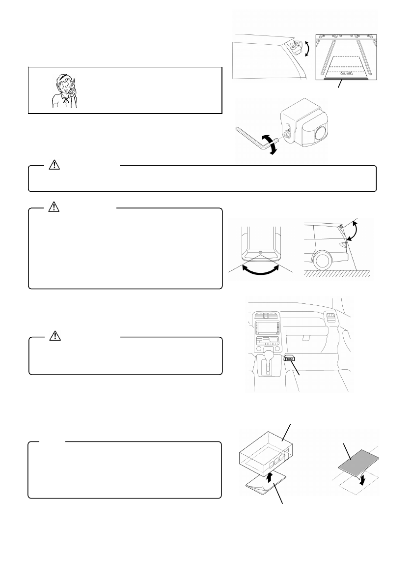
4. Adjust the camera angle so that the extreme rear
end of the vehicle (bumper, rear window, and
liftgate.) is displayed at the bottom of the monitor.
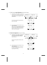
• After adjusting the angle, tighten the screws
with them seated at the lower end of the
oblong holes in the bracket on each side.
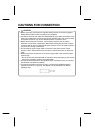
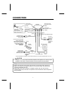
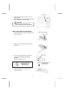
5. Locate a position to install the ECU box where all
the cables are within connection reach.
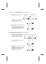
6. Peel off the paper backing from the Hook-and-loop
fastener (1 set.), adhere each piece to the bottom of
the ECU box, and install the ECU box in the
position determined in Step 5.
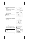
• If the rough surface of the Hook-and-loop fastener
attached to the bottom of the ECU box adheres to
floor without need for the mating piece, attach the
ECU box directly to the vehicle floor without using
the mating piece.
• Verify the tightness of the screws and tighten them more if necessary.
CAUTION
Tighten
Loosen
• Avoid installing near the ventilators for the
heater.
CAUTION
Approx.
105°
Approx. 135°
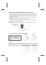
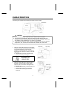
• After installing the camera, the screen displays
an approximate 135-degree view between the
left and right, and an approximate 105-degree
view between up and down. The rear view back
up camera system is a device designed only to
assist the driver. The driver must take full
precautions to confirm the safety and conditions
around the vehicle.
CAUTION
• There are separate surfaces for each p
i
ece
of Hook-and-loop fastener. Attach the rough
surface to the bottom of the ECU box, and
the soft surface to the location where the
ECU box is to be installed.
Note
ECU box
Hook-and-loop
fastener
(Rough side)
Hook-and-loop
fastener (Soft side)
Floor
ECU box
Extreme rear end of vehicle
(bumper etc.)
Need help? Call
1-800-421-5013