


9
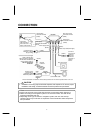
CONNECTION
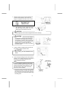
• Installation and wiring require technical expertise and experience. To ensure proper
installation and safety, consult the dealer where the product was purchased.
CAUTION
•
A
lways use the same type of fuse with the same current rating when replacing it.
• When connecting to a navigation system or an external monitor, also refer to the
manual provided with the unit.
• Depending on the type of vehicle or navigation system, the rear view back up
camera system may not function as expected. Consult the dealer where the product
was purchased.
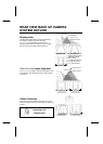
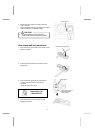
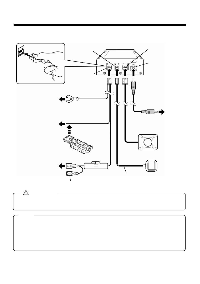
Notes
Connect firmly to a
metal part of vehicle
(for grounding)
Connect to the reverse signal
cable of vehicle using
self-lock conductor included
with the Rear View Back up
Camera System. Refer to
“How to use self-lock
conductor”.
Power supply cable
(Brown)
(Brown)
Connect to
Camera input
terminal or
video input
terminal on
navigation or
external
monitor.
Control
s
witch
Control
s
witch cable
Self-lock
conductor
Fuse(1A)
Video output cable (RCA Type)
(Yellow)
ECU box
(Yellow)
(Red)
(Black)
Connect to point
where power is
supplied at ignition
switch ACC position.
This terminal allows connection of other accessory devices. Do not remove cap/sleeve when not in use.
(Black)
(Green)
Rear view camera
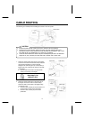
Connect the
cable according
to the color and
shape of the terminal
Control switch
connection terminal
(Green)
Rear view camera
connection terminal
(Black)
Video output
connection terminal
(Yellow)
Power supply
connection terminal
(Brown)