


Installation & Programming Manual FX & VFX Series Inverter/Charger System Copyright 2003 OutBack Power Systems, Inc.
900-0027-1 19009 62
nd
Ave NE, Arlington WA 98223 USA
Page 46 Rev 7.2 08/26/05 Tel 360 435 6030 Fax 360 435 6019
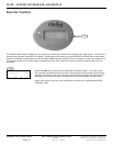
MATE SCREENS
ERROR MENU
The ERROR section allows the user to check the cause of an error condition. When an error has occurred, the red error LED indicator
in the FX’s wiring compartment will be illuminated (not to be confused with a blinking “ERROR” LED that indicates a WARNING). If an
error occurs, the FX will cease operation and the MATE will display an error screen. Pressing
<VIEW ERROR> from this screen brings
the user to the 1
st
screen of a list of error causes that will be available by pressing the DOWN button. The presence of the word “YES”
to the right of the appropriate cause indicates that this error has occurred. It is possible for multiple errors to occur simultaneously.
Check every error condition to make sure. An error can be cleared by pressing the
<INV> button on the MATE and then turning the FX
<OFF> and then <ON>. The inverter automatically resets from over-temperature and low or high battery voltage conditions.
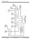
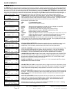
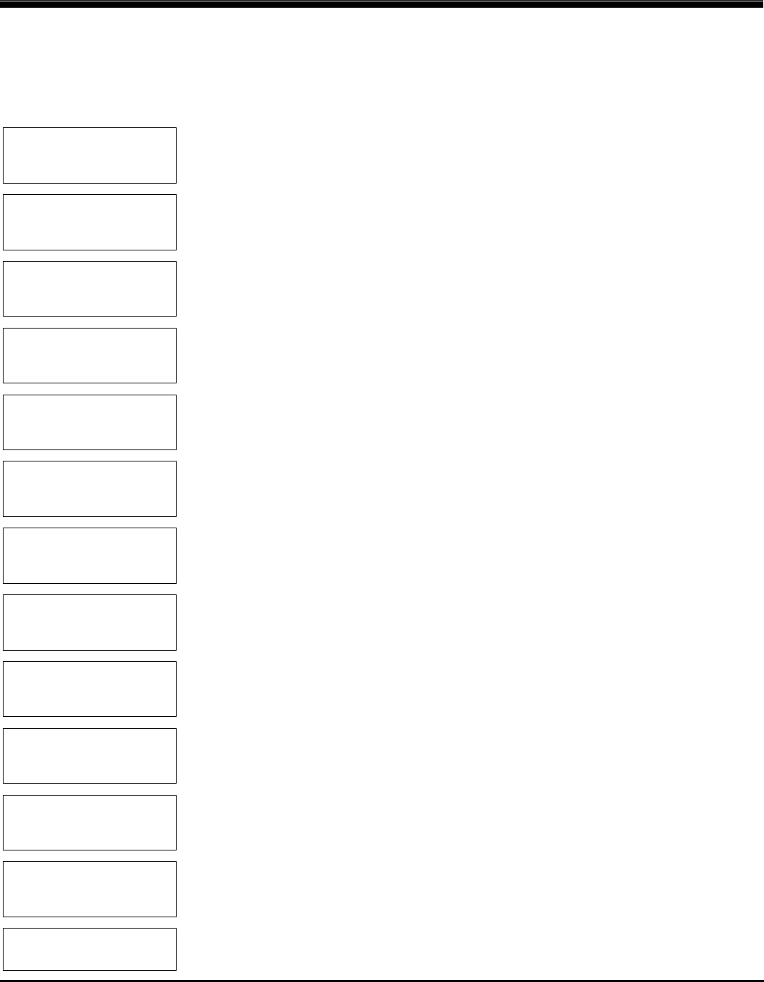
MAIN----------------
6:54:42P
SUM STATUS SETUP ADV
↓
STATUS--------------
choose product:
FX MX
↓
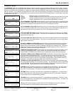
STATUS/FX/PAGE1-----
choose category:
MODES METER BATT PG2
↓
STATUS/FX/PAGE2-----
choose category:
PG1 ERROR WARN PG3
↓
STATUS/FX/ERROR—-P00
low ac output No
voltage
DOWN STATUS PORT
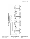
↓
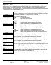
STATUS/FX/ERROR—-P00
stacking No
error detected
DOWN UP TOP PORT
↓
STATUS/FX/ERROR—-P00
inverter No
overtemp
DOWN UP TOP PORT
↓
STATUS/FX/ERROR—-P00
low battery No
voltage
DOWN UP TOP PORT
↓
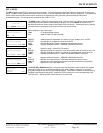
STATUS/FX/ERROR—-P00
phase loss No
error
DOWN UP TOP PORT
↓
STATUS/FX/ERROR—-P00
high battery No
voltage
DOWN UP TOP PORT
↓
STATUS/FX/ERROR—-P00
ac output No
shorted
DOWN UP TOP PORT
↓
STATUS/FX/ERROR—-P00
ac output No
backfeed
DOWN UP TOP PORT
↓
STATUS/FX/ERROR—-P00
end of error menu
UP TOP STATUS
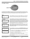
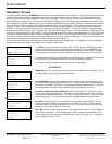
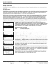
The MAIN screen is where the menu system starts. The four words in the bottom line of the
display correspond to the four buttons located below the display. The word in
BOLD on the bottom
line indicates the selection used to advance the display to the next screen. Pressing the left two
buttons simultaneously from anywhere in the menu will return you to this screen.
Allows selection of the product type:
<FX> FX inverter/charger system
MX MX60 PV MPPT charge controller
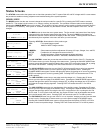
MODES Status and allows adjustment of Inverter, AC input, Charger, Aux, and EQ
METER Provides the AC voltages and currents of the FX
BATT Provides the battery voltage and charger set points and timers
<PG2> Displays additional sections – ERRORS, WARNINGS and PG3
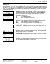
PG1 Returns to page 1 of the STATUS section
<ERROR> Displays the different causes for errors and qualifies each cause with a Yes or No
WARN Displays the different causes for warnings and qualifies each with a Yes or No
PG3 Displays additional sections – reason for last DISCONNECT and SELL
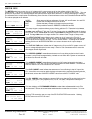
LOW AC OUTPUT VOLTAGE indicates that the inverter was not able to maintain adequate AC
output voltage (105 VAC or above) to power the loads connected. This is typically caused by the
load demanding more power than the inverter is able to deliver.
STACKING ERROR DETECTED indicates that a problem has occurred with the communication
cabling between stacked FX’s, or if the FX’s are stacked incorrectly. Check the stacking
programming. If this condition persists contact your dealer for servicing instructions.
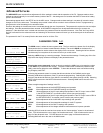
INVERTER OVERTEMP indicates that the FX reached its maximum allowed operating temp. This
can be caused by powering large AC loads or charging for too long. It can also be caused by
restricting the amount of air which is able to flow around the casting or operation in high temp
environments. The FX will automatically reset and resume operation once it cools down.
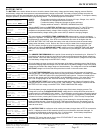
LOW BATTERY VOLTAGE indicates that the battery voltage dropped below the LOW BATTERY
CUT-OUT VOLTAGE set point (default of 10.5 volts for a 12 volt FX) for 5 minutes. The inverter
will restart once the battery voltage exceeds the LOW BATTERY CUT-IN VOLTAGE set point
(default of 12.5 volts for a 12 volt FX) for 10 minutes.
PHASE LOSS ERROR is not operational at this time. If a ‘Yes’ accompanies this Error, please
disregard and look for other error causes.
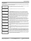
HIGH BATTERY VOLTAGE indicates that the battery voltage rose above the high battery voltage
level (default of 20 volts for a 12 volt FX) for 10 seconds. The inverter will restart once the battery
voltage drops below the high battery voltage (default of 20 volts for a 12 volt FX) for 1 second.
AC OUTPUT SHORTED indicates that the inverter immediately reached its maximum current and
shut down. This is usually caused by a short circuit condition (hence the AC OUTPUT SHORTED
label) but can also be caused by attempting to operate a load which far exceeds the inverter
output capability.
AC OUTPUT BACKFEED indicates that another AC source of power was connected to the AC
output of the FX. Usually this is an installation issue. It often occurs when there is an X-240
transformer in the system that hasn’t been installed properly. Also, check that there are no
connections between the AC input and AC output circuitry.
Selecting TOP returns the user to the top of the STATUS/FX/ERROR menu section. Selecting
STATUS returns to the first page of the STATUS screen.