


Copyright 2003 OutBack Power Systems, Inc. FX & VFX Series Inverter/Charger System Installation & Programming Manual
19009 62
nd
Ave NE, Arlington WA 98223 USA 900-0027-1
Tel 360 435 6030 Fax 360 435 6019
Rev 7.2 08/26/05 Page 17
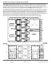
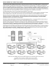
FX SYSTEM CONFIGURATIONS
The FX System Configuration section shows diagrams of some typical system configurations using the FX. These diagrams are for
non-Mobile FX installations only. Below these diagrams are notes for how to change each diagrams to accommodate a
Mobile installation. There are diagrams for a single FX, two FX’s in series or series/parallel (see NOTE below), two FX’s in parallel,
four FX’s in series/parallel (see NOTE below), four FX’s in parallel, and a 3-phase system. The diagrams show the proper breakers
and wiring for the AC side of the installations as well as connections to the HUB, MATE and X-240 (if applicable). Also included is
information on the maximum continuous power of the systems and proper DC breaker sizes. This information is dependent on whether
the FX’s are sealed or vented and on the system’s battery voltage.
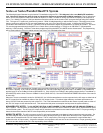
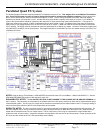
NOTE: Stacking FX’s in series/parallel means that there are FX’s directly connected to two separate 120VAC output legs. These two
120VAC output legs produce 240VAC between them (the series portion). By connecting the X-240 autotransformer between the two
120VAC output legs, these legs are magnetically coupled (indirectly connected). This allows all of the FX’s to power either of the
120VAC output legs (the parallel portion). Series/parallel stacking requires the use of the X-240 autotransformer and must use
“OutBack” stacking programming.
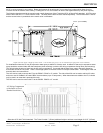
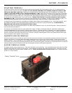
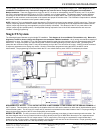
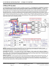
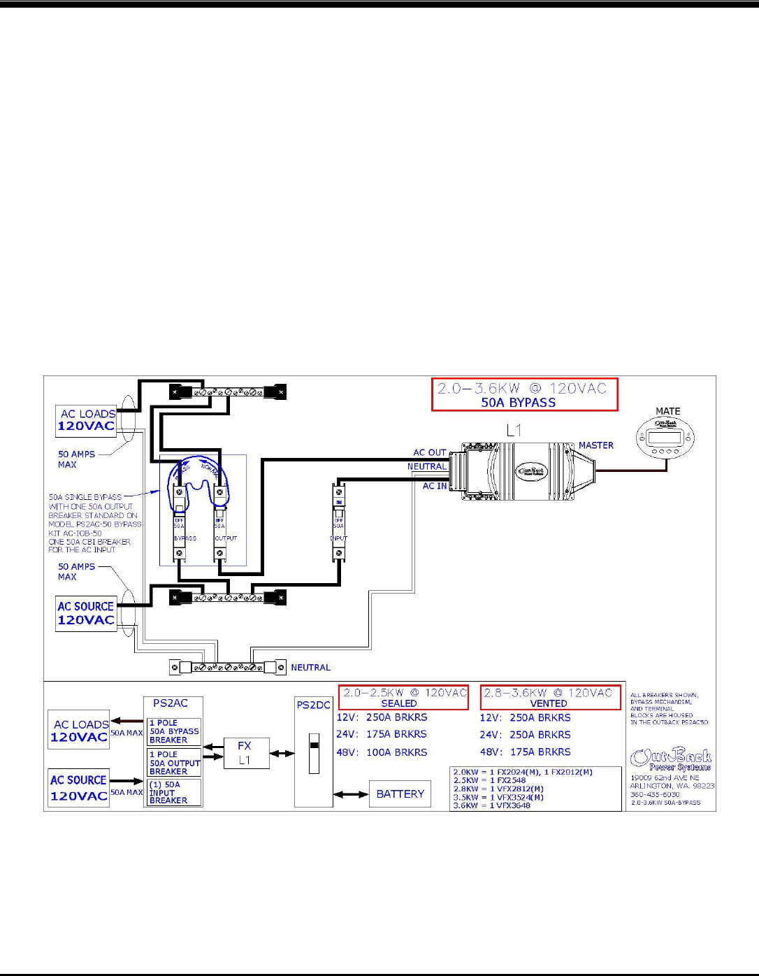
Single FX System
The following diagram illustrates a typical single FX installation. This diagram is for a non-Mobile FX installation only. Below this
diagram are notes for how to change this diagram to accommodate a Mobile installation. All AC wiring must handle a capacity of
50 amps AC or more. For ‘Mobile’ FX’s, a 30A input breaker should be used due to the maximum AC input pass-through rating of the
Mobile FX’s. A single FX system can continuously power 2-3.6KW of loads depending on which model is used. Connecting more
power than the continuous rating of the FX may cause breakers to trip or the FX to shut off its AC output. A MATE must be connected
to adjust any parameters or to display any meters. Once the FX has been programmed using the MATE, the MATE can be
disconnected. The programming will be saved within the FX’s non-volatile memory even if the FX is completely shut down.
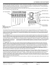
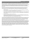
NON-MOBILE FX NOTES: The AC OUTPUT NEUTRAL IS NOT BONDED TO THE CHASSIS OR THE GROUND TERMINAL of
the FX system. This connection is to be made by the installer either in the AC service entrance or within the AC load distribution panel
of the electrical system. The AC input, AC output and DC terminals are isolated from the metal chassis of the FX. Proper grounding of
these circuits and the chassis of the FX is the responsibility of the installer.
MOBILE FX NOTES: The AC input source to the FX (grid and/or generator) must have an internal neutral-ground connection. On
the above diagram the AC source’s neutral conductor must go directly to the FXs AC NEUTRAL IN terminal or to a separate neutral
busbar that is isolated from the FX’s AC output neutral. The AC output of the FX must go to a separate AC output busbar that is
isolated from the AC input neutral. A bypass mechanism must bypass the AC source’s hot and neutral wires. Proper grounding of the
DC circuit and the chassis of the FX is the responsibility of the installer.