


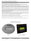

Installation & Programming Manual FX & VFX Series Inverter/Charger System Copyright 2003 OutBack Power Systems, Inc.
900-0027-1 19009 62
nd
Ave NE, Arlington WA 98223 USA
Page 30 Rev 7.2 08/26/05 Tel 360 435 6030 Fax 360 435 6019
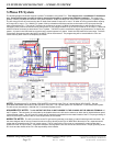
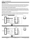
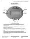
STACKING INSTRUCTIONS
System Examples (Continued)
By making this FX the 1
st
rank slave, we are turning both Legs “On” directly, thus producing 240VAC without using the X-240.
If you have a system that is different from this example then press the PORT button until you get to a slave FX that is in series (“OB
Slave L2”) with the master.
On this screen the setting from the factory should be set to 1 which indicates the 1
st
rank slave. If it’s anything other than 1 then press
the DEC button until it becomes 1. Press the PORT button until you reach P02 to talk to the port 2 FX.
If you have a system that is different from this example then press the PORT button until you get to a slave FX that is in parallel (“OB
Slave L1”) with the master.
Press the INC button to change the “POWER SAVE LEVEL SLAVE ADJUST ONLY” to 2 which is the 2
nd
rank slave. Press the PORT
button twice to talk to the port 4 FX.
If you have a system that is different from this example then press the PORT button until you get to the next slave FX that is in series
(“OB Slave L2”) with the master.
Press the INC button until the setting is 3 for 3
rd
rank slave.
Any additional FX’s in the system can be programmed by pressing the PORT button to get to the next FX and then press INC until the
setting is 4 for the 4
th
rank slave. Continue this process, making sure each FX has its own “Slave Rank”, until you have set all FX’s.
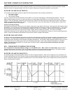
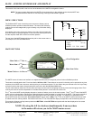
Let’s back track a little by going to the “POWER SAVE LEVEL MASTER ADJUST ONLY” menu. Do this by pressing the DOWN
button, TOP button, then DOWN button. Verify that the screen you are on now is the “POWER SAVE LEVEL MASTER ADJUST
ONLY” screen and change the port to P01. Turn on all of your FX’s AC Output breakers. The master FX’s “Inverter” LED should be
solid and all the slaves “Inverter” LED’s should be blinking. Adjust the “POWER SAVE LEVEL MASTER ADJUST ONLY” from 0 to 1
and watch the 1
st
slave’s (port 3) “Inverter” LED go solid. When the “Inverter” LED is on solid, this means that the inverter is on. When
the “Inverter” LED on the slave is blinking, this means the FX is asleep. Adjust the “POWER SAVE LEVEL MASTER ADJUST ONLY”
to 2 and watch the 2
nd
slave’s (port 2) “Inverter” LED turn on. Adjust the “POWER SAVE LEVEL MASTER ADJUST ONLY” to 3 and
watch the 3
rd
slave’s (port 4) “Inverter” LED turn on. If you have more than three slaves then keep increasing the value in the “POWER
SAVE LEVEL MASTER ADJUST ONLY” screen and verify that each slave’s “Inverter” LED comes on as expected. You have now
verified that all FX’s are stacked correctly so adjust the “POWER SAVE LEVEL MASTER ADJUST ONLY” back down to 0 and have
fun with your system!
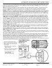
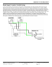
3-PHASE STACKED SYSTEM (3 FX’S ONLY)
This type of system will include only three FX’s and must be set up as described here. Turn off all AC Output and AC Input breakers
before powering up FX’s. In 3-phase stacking, I am assuming that the top FX is plugged into port 1 of the HUB, the 2
nd
FX down is
plugged into port 2 and the 3
rd
FX down is plugged into port 3 (This is not a rule, just for simplicity). The HUB has a jumper on it that
needs to be changed for 3-phase stacking (refer to the HUB manual). Using the MATE, go to the stacking menu (explained earlier in
the “Stacking Instructions” section). You are now at the 1
st
stacking menu called “Stack Phase”. In the upper right hand corner of the
mate screen will always be the HUB port number of the FX you’re working with at the time. Let’s start out with the FX that’s on port 1.
If something other than P01 appears in the upper right hand corner then press the PORT button until P01 appears. Set the “Stack
Phase” of the port 1 FX to “3ph Master”. The Master FX is considered phase A. Press the PORT button and verify that the label in the
upper right hand corner displays P02. We are still in the “Stack Phase” menu but we are now talking to the FX on port 2. Push the INC
button five times to set the “Stack Phase” to “3ph Slave”. Now you’ve set this FX (P02) as phase B, producing 208VAC between itself
and the master (P01). Press the PORT button again and verify that the label in the upper right hand corner displays P03. We are still
in the “Stack Phase” menu but we are now talking to the FX on port 3. Push the INC button five times to set the “Stack Phase” to “3ph
Slave”. Now you’ve set this FX (P03) as phase C, producing 208VAC between itself and the master (P01) and also 208VAC between
itself and the FX on phase B. The next two screens in the STACK menu do not apply to a 3-phase system, so you need not worry
about them. Remember that the AC input to a 3-phase system must be a 3-phase source (generator or grid). Have fun with your
system!