


Copyright 2003 OutBack Power Systems, Inc. FX & VFX Series Inverter/Charger System Installation & Programming Manual
19009 62
nd
Ave NE, Arlington WA 98223 USA 900-0027-1
Tel 360 435 6030 Fax 360 435 6019
Rev 7.2 08/26/05 Page 13
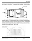
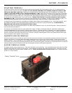
BATTERY - FX CABLING
DC BATTERY TERMINALS
The DC terminals are made from solid brass with a stainless steel threaded stud. The threads are M8 x 1.25. The black terminal is
negative and the red terminal is positive. DO NOT PUT ANY WASHERS BETWEEN THE TERMINAL MOUNTING SURFACE AND
THE ACTUAL BATTERY CABLE LUG. Place the lug, washers and nut in the following order: Lug, Flat Washer, Lock Washer, Nut.
TORQUE TO 60 INCH-POUNDS (5 FOOT POUNDS) MAXIMUM (6.77 NM). Mobile FXs come with a fuse for protection of the battery
cables connected to the FX. If used, the fuse must be mounted to the positive terminal (red). The hole of the battery cable lugs must
be at least 10mm to properly fit the fuse. If using a 3/8” hole, file this down to produce a 10mm hole. Place the lug, fuse and fuse nut
on the terminal in the following order: Fuse, Lug, Fuse Nut. TORQUE THE FUSE NUT TO 60 INCH-POUNDS (5 FOOT POUNDS)
MAXIMUM (6.77 NM). Too much torque on the fuse nut will cause the fuse nut to shatter! This will put your installation on hold. It is
recommended that a separate means of disconnecting the positive battery cable be included in systems that use fuses.
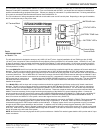
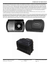
UL listed DC rated circuit breakers are available from OutBack Power Systems with amperages of 100, 175 and 250 amps DC. All of
the OutBack DC breakers come with threaded studs out the back for connection to ring type terminal lugs. ALWAYS INSTALL
BREAKERS OR FUSES WITHIN THE POSITIVE BATTERY CABLE.
OutBack also offers stud mounted fuses (SMF) for non-NEC code installations in 100, 175, and 250 amp sizes. These are the same
fuses included with the Mobile FX.
The minimum recommended cable size varies with the DC voltage. VFX2812, VFX2812M, FX2012T, FX2012MT, VFX3524 and
VFX3524M installations must use 4/0 AWG (120mm2) cable minimum. VFX3648, FX2524T, FX2524MT, and FX3048T installations
can use 2/0 AWG (70mm2) cable as long as the distances are short (less than 10 feet / 3 meters per cable). If longer distances are
required, increase the cable size to the next size as a minimum. Keep the cables together as much as possible for their entire length.
Tying or taping the cables together is also advisable.
EQUIPMENT GROUND TERMINALS
A set-screw type box lug is provided near the DC terminals to allow the connection of an equipment grounding conductor for the metal
chassis of the inverter. It is located behind the battery negative terminal on the top of the inverter casting. A green ground symbol
marks the location. When mounting an FX to a PS2MP or PS4MP, a star washer located under one of the four screws that connect the
FXs chassis to the mounting plate provides grounding of the FX to the mounting plate. Connection to the ground terminal is not required
if the star washer is used to connect the FX to the mounting plate and the mounting plate is grounded.
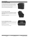
BATTERY TERMINAL COVERS
The battery terminal covers simply snap on. They are a little brittle, so use some care. Use a flat bladed screw driver blade in the slots
provided on the sides of the cover to pry the cap off. If the installation is exposed, DC conduit may be required. Connection of 2-inch
conduit is possible when the DCA option is added to the FX. Always install the Battery Terminal Covers, even in systems that have
an DCC or a Turbo included.
Battery Terminal Covers