


Installation & Programming Manual FX & VFX Series Inverter/Charger System Copyright 2003 OutBack Power Systems, Inc.
900-0027-1 19009 62
nd
Ave NE, Arlington WA 98223 USA
Page 16 Rev 7.2 08/26/05 Tel 360 435 6030 Fax 360 435 6019
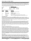
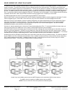
HUB COMMUNICATION MANAGER
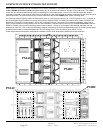
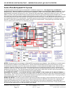
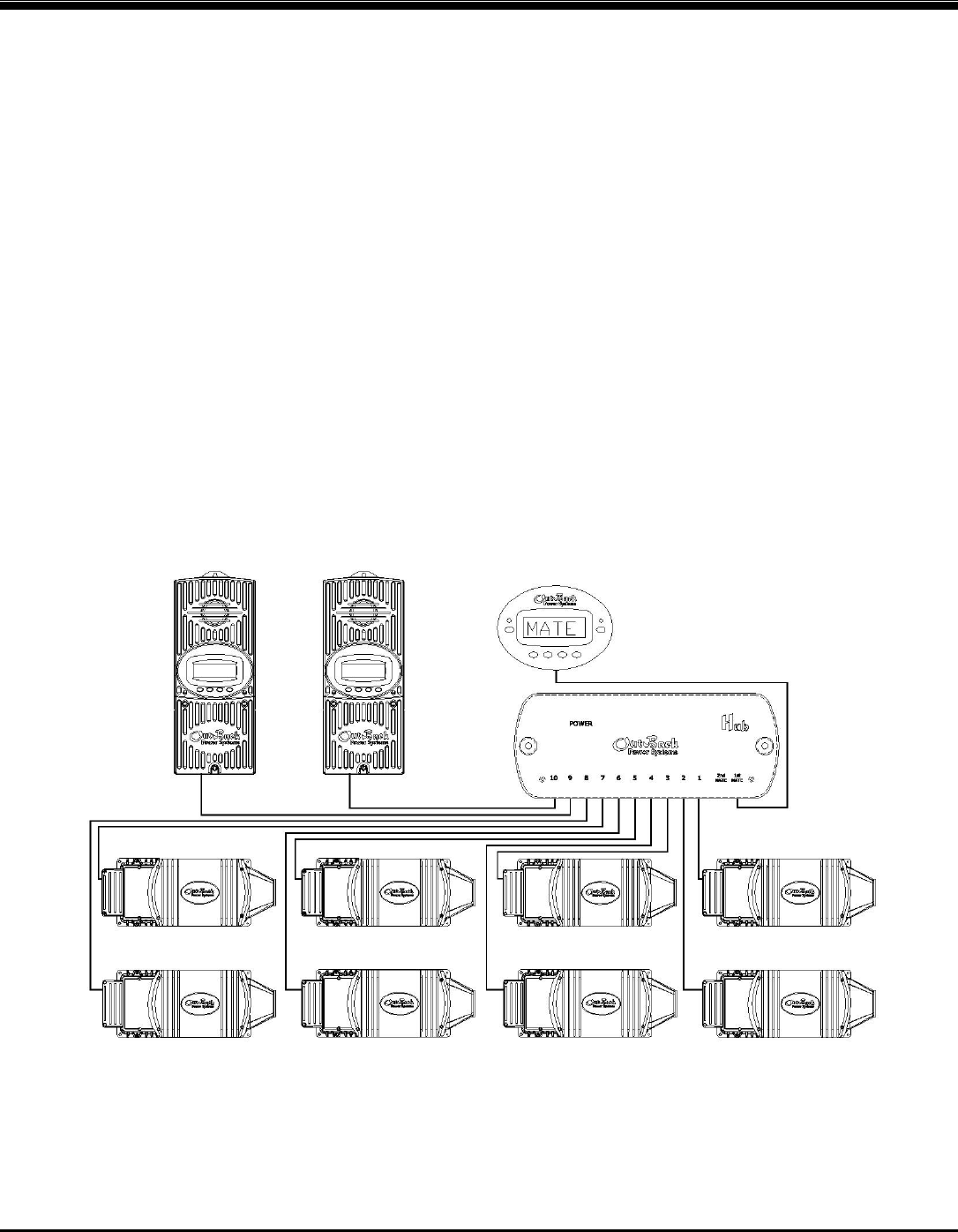
The HUB communication manager allows the MATE to control and monitor a maximum of ten OutBack products. Currently the HUB
comes in two types. The HUB-4 can connect up to four Outback products (FX’s and/or MX-60’s). The HUB-10 (shown below) can
connect up to ten Outback products (FX’s and/or MX-60’s). The FX’s can be operated in a stacked or independent configuration. If the
FX’s are to be stacked, the HUB must be part of the system. In a stacked configuration, the Master FX must be plugged into port #1 of
the HUB. The Slave inverters must use the following ports (example: for 8 inverters and 2 MX-60’s, the Master must be plugged into
Port 1, and the seven Slaves must be plugged into Ports 2-8. The MX-60’s can use Ports 9&10). Future OutBack products will also be
compatible with the HUB. When using the HUB, the MATE must be plugged into the 1st MATE port of the HUB.
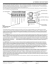
The HUB manages both the inter-FX communications and the MATE-FX communication.
When a HUB is used in conjuncture with the RTS, the RTS (Remote Temperature Sensor) must be plugged into the Master FX which
must be plugged into port 1 of the HUB. If this is the case, only one RTS is required for all devices plugged into the HUB.
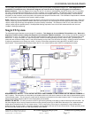
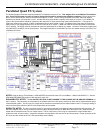
When two or more FX’s are stacked in a series or parallel configuration, the system automatically turns off any excess slave FX’s to
save power and maximize conversion efficiency. This power save system is fully automatic and works with or without the MATE
connected to the system. Some programming is required when more than two FXs are stacked together. See the STACKING
INFORMATION section of this manual for more information.
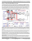
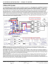
Currently on 3-phase systems there is a limit of one FX per phase (totaling three FX’s). To convert the HUB into 3-phase mode, you
must move the jumper on the HUB to the “3-PH” position. See the HUB instruction manual for details.
One MATE system controller and display can be connected to the HUB. Although there are two Mate ports on the HUB, only the 1st
Mate port is currently operational. The MATE can be located up to 1000 feet (305 meters) from the HUB / system location. Cabling
from the HUB to the MATE is completed using standard CAT-5 type ethernet cable with RJ45 modular 8 conductor jacks. This wiring is
considered to be low voltage / limited energy circuitry. Refer to the MATE manual for more information on the MATE.
All cabling from the FX and MX60 communication ports to the HUB is made with CAT-5 type ethernet cabling. The maximum distance
from the HUB-4 to the FX or MX-60 should be less than 10 feet. OutBack includes two 3-foot (1 meter) and two 6-foot (2 meter) long
CAT-5 cables standard with the HUB-4. OutBack includes two 3-foot (1 meter) long and four 6-foot (2 meter) long CAT-5 cables
standard with the HUB-10. Check with your OutBack dealer for additional cables.
A total of up to ten OutBack products plus one MATE displays can be used with a HUB-10 (shown above).
The HUB-4 will only accept four OutBack products plus one MATE.
NOTE: There is a limit of ten FX’s when operated as a stacked system.
MX60
HUB-10
MASTER
SLAVE
SLAVE
SLAVE
SLAVE
SLAVE
SLAVE
SLAVE
MX60
MATE