


Installation & Programming Manual FX & VFX Series Inverter/Charger System Copyright 2003 OutBack Power Systems, Inc.
900-0027-1 19009 62
nd
Ave NE, Arlington WA 98223 USA
Page 26 Rev 7.2 08/26/05 Tel 360 435 6030 Fax 360 435 6019
STACKING INFORMATION
Classic, OutBack, and 3-Phase Stacking Methods
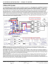
OutBack Power Systems offers four different ways to stack multiple FX’s (up to 10 for single or split phase systems, only 3 for three-
phase systems). The first thing to consider is if you want all of the FX’s in parallel (FX’s on same AC Output Leg producing 120VAC
only), in series (FX’s divided between two AC Output Legs producing 120VAC on each Leg and 240VAC between the two Legs), or in
3-phase (maximum of three FX’s, one on each AC Output Leg, producing 120VAC on each Leg and 208VAC between each set of
Legs). A HUB-4 or HUB-10 must be included to stack FX’s.
If you choose to stack the FX’s in series, the second thing to consider is how many FX’s you will use. If you are series stacking three
to ten FX’s, you must use “OutBack” stacking and include an X-240 autotransformer. If you are series stacking only two FX’s, you can
choose between “Classic” stacking and “OutBack” stacking. Keep in mind that if you choose to series stack FX’s using “OutBack”
stacking, you must include an X-240 autotransformer in the system. Below is an explanation of each type of system.
The next four pages explain the Stacking menu and how to program the various types of stacked systems.
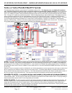
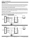
PARALLEL (OUTBACK): This stacking method pertains to a system that has two to ten FX’s all connected to the same 120VAC
Output Leg. The system can be programmed such that only one FX (the Master) stays “On” and the rest of the FX’s (the Slaves) are
asleep. The Slaves come on only when the power requirement is high enough that the Master FX calls on the Slave FX’s to help with
the load. It is also possible to program the system to keep any number of FX’s “On” while the remaining FX’s are asleep. The AC Input
source (usually a generator or utility grid) must be 120VAC or stepped-down to 120VAC form a 240VAC source using the X-240
autotransformer.
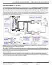
SERIES (CLASSIC): This stacking method pertain to a system that has only two FX’s and two 120VAC Output Legs that will produce
240VAC between them. In this system the Master FX and the Slave FX operate independently from each other. In other words, each
FX will power its own 120VAC Output Leg but if any 240VAC loads need to be powered both FX’s will be used. The AC Input source
(generator or grid) must be 240VAC for both Legs to be powered.
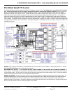
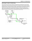
SERIES (OUTBACK): This stacking method pertains to a system that has two to ten FX’s connected to two 120VAC Output Legs that
will produce 240VAC between them. In this stacking method the FX’s will be connected to either of the two AC Output Legs (usually
half of the FX’s on each Leg). Connected between the AC Output Legs will be an X-240 autotransformer that gets installed in the
PSAC (or PS2AC). The X-240 can perform two operations that a “classically” stacked system cannot perform and can handle more
that two FX’s. First, it can produce 240VAC from one Leg if that 240VAC load is small enough. This saves power in the long run by
keeping the FX’s on the other Leg in “sleep” mode. Secondly, the X-240 allows each FX to power loads on the Leg of which it is not
directly connected. This allow the Master FX on Leg 1 to power loads on Leg 2 without “waking” and Slave FX’s unnecessarily. The
biggest advantage is that this system is very tolerant of imbalanced loads on the two 120 vac Legs on the AC output. By the magic of
the X-240 autotransformer, together with the control method used in the FX, the AC loads are balanced on the two Legs automatically.
This maximizes the efficiency of the FX system and allows larger loads to be operated without overloading one of the FX’s. The AC
Input source (generator or grid) must be 240VAC for both Legs to be powered and for no faults to occur.
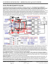
3-PHASE: This stacking method pertains to a system that has three FX’s connected to three 120VAC Output Legs that will produce
208VAC between any two Legs of the 3-phase system. In this stacking method only three FX’s can be used. Each of the three FX’s
will be connected to its own 120VAC Output Leg. To set the system up properly an adjustment to the HUB is necessary. Within the
HUB is a jumper that needs to be changed in order for the system to operate correctly. See the HUB manual for instructions on this
procedure. The AC Input source (generator or grid) must be a 120VAC/208VAC 3-phase source connected to the AC Input terminals of
the three FX’s.
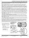
X-240 AUTOTRANSFORMER CAPACITY
The X-240 autotransformer option is rated at 4000 VA continuously and consumes about 12 watts. The PSAC and PS2AC enclosures
include mounting for this option and the PSAC (not the PS2AC) also includes a space to allow the addition of two 12 vdc powered 4
inch muffin fans to increase the continuous power rating of the X-240. This fan can be powered directly from the AUX output of an FX
when the AUX output function has been programmed for “COOLFAN” (default) mode. This enables the 12 vdc fan to turn on
automatically when the FX’s are powering heavy loads. With the additional air flow on the X240, it can handle a maximum of 6000 VA
continuously. The X-240 option includes a 25 amp, 2-pole circuit breaker which is rated for 100% continuous duty applications. It may
be necessary to use two X-240’s in systems that include more than four FX’s (depending on how much power needs to be transferred
from one AC Output Leg to the other AC Output Leg).
In the balancing transformer application with series stacked inverters, the X-240 is able to transfer up to 3000 VA from one of the 120
VAC output legs to the other 120 VAC output leg. Power higher than 3000 watts can be transferred through the X-240 for starting loads
that require large surges but should not be used on a continuous basis.