


300-302 Series Page 9 of 31
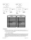
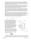
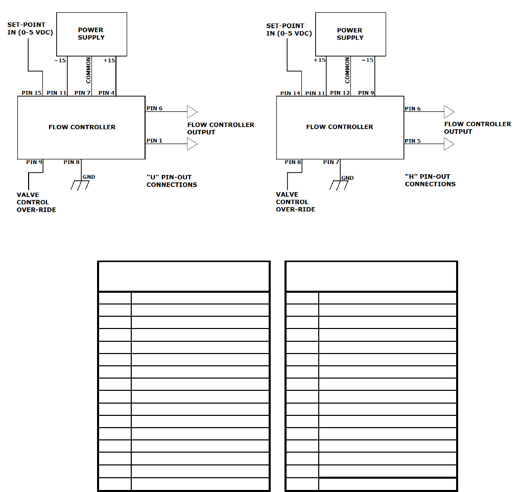
Figures 2.1/2.2, and Tables 2.1/2.2, show the 300/302 pin out.
Pin # Pin #
1 Signal Common 1 Do not use
2 Do not use 2 Do not use
3 Do not use 3 Do not use
4 +15 VDC 4 Do not use
5 5 Signal Common
6 Output 0-5 VDC (4-20mA) 6 Output 0-5 VDC (4-20mA)
7 Signal Common 7 Case Ground
8 Case Ground 8 Valve Override
9 Valve Override 9 -15VDC
10 10 Do not use
11 -15VDC 11 +15VDC
12 External Input 12 Signal Common
13 Signal Common 13 External Input
14 Signal Common 14 Set Point 0-5 VDC (4-20mA)
15 Set Point 0-5 VDC (4-20mA) 15 Do not use
Table 2.1
"U" Pin-Out
Table 2.2
"H" Pin-Out
2.6. Operation
The standard instrument output is a 0 - 5 VDC out and the signal is proportional to the flow i.e., 0
volts = zero flow and 5 volts = 100% of rated flow. The 4 - 20 mA option is also proportional to flow, 4
mA = zero flow and 20 mA = 100% of rated flow.
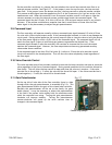
2.6.1. Operating Conditions
For proper operation, the combination of ambient temperature and gas temperature must be such that
the flow meter temperature remains between 0 and 60°C. (Most accurate measurement of flow will
be obtained if the flow meter is zeroed at operating temperature as temperature shifts result in some
zero offset.) The Hastings 300 series instrument is intended for use in non-condensing environments
only. Condensate or any other liquids which enter the flow meter may destroy its electronic
components.
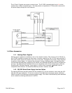
Fig. 2.1 Fig. 2.2