


300-302 Series Page 23 of 31
Action: Shut off all flow. For the standard 0-5VDC output, adjust the zero potentiometer
located on the upper right inlet side of the flow meter until the meter indicates zero.
For the optional 4-20 mA output, adjust the zero potentiometer so that the meter
indicates slightly more than 4 mA, i.e. 4.03 to 4.05 mA. This slight positive
adjustment ensures that the 4-20 mA transmitter is not in its cut-off region. The error
induced by this adjustment is approximately 0.3% of full scale.
Symptom: Flow meter is out of calibration and non-linear.
Cause: Leaks in the gas inlet or outlet fittings.
Action: Check all fittings for leaks by placing soap solution on all fittings between gas supply
and final destination of gas. Check flow meter for leaks. Replace if required or
recalibrate as necessary.
Symptom: Little or no flow, even when the valve is in over-ride OPEN.
Cause: Blocked orifice or incorrect pressure across the Flowcontroller
Action: Verify that the pressure drop originally specified on the instrument is across the
instrument. If the differential pressure across the instrument is correct, the orifice may
be obstructed. Remove all gas pressure and shut off power supply. Remove the valve.
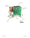
4.2. Adjustments
4.2.1. Calibration Procedure
1. Calibration must take place with cover firmly in place.
2. Connect power to “D” connector as specified in Section
2.5. Allow the instrument to warm up for 60 minutes with
10% of full scale flow.
3. Completely shut off the flow and wait for 2 minutes. For
the standard 0-5VDC output, adjust the zero
potentiometer located on the lower inlet side of the flow
meter until the meter indicates zero. For the optional 4-
20 mA output, adjust the zero potentiometer so that the
meter indicates slightly more than 4 mA, i.e. 4.03 to 4.05
mA. This slight positive adjustment ensures that the 4-20
mA transmitter is not in its cut-off region. The error
induced by this adjustment is approximately 0.3% of full
scale.
4. Turn on gas supply to inlet of instrument and adjust the flow rate to the desired full scale
flow as indicated by a reference flow meter/controller.
5. Adjust Span pot until the indicated flow reads full scale (5.00VDC or 20 mA). Perform this
step only if a calibrated reference flow meter is available.
6. Record flow meter/controller and flow reference outputs for flow rates of 20%, 40%, 60%,
80% and 100% and make sure data are within ± 0.75% 3σ of full scale.
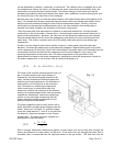
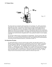
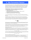
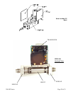
4.3. End Cap Removal
The end cap on the inlet side must be removed to gain access to shunt assembly. First remove power
and shut off the supply of gas to the instrument. Disconnect the fittings on the inlet and outlet sides
of the transducer and remove it from the system plumbing. Remove the four Allen head screws
holding the end cap to the instrument. Carefully remove the end cap, nickel gasket, spacer, and
shunt, noting their order and proper orientation. The shunt can be severely damaged if dropped.
Examine the shunt. If damaged, dirty or blocked, clean and replace as applicable. Reassemble in the
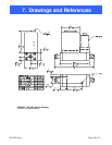
Fig. 4.1