


300-302 Series Page 18 of 31
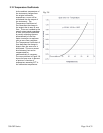
desired to ensure a stable instrument, there must be some matching between the linear volumetric
flow versus pressure drop of the sensor and the shape of the volumetric flow versus pressure drop of
the shunt. Most instruments employ
Poiseuille’s law and use some sort of
multi-passage device that creates
laminar flow between the upstream
sensor inlet and the downstream outlet.
This makes the volumetric flow versus
pressure drop curve primarily linear, but
there are other effects which introduce
higher order terms.
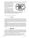
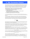
Most flow transducers are designed such
that the outlet plenum has a smaller
diameter than the inlet plenum. This
eases the insertion and containment of
the shunt between the sensor inlet point
and the sensor outlet point. If the shunt
is removed, the energy of the gas must be conserved when passing from the inlet
plenum to the outlet plenum. From Bernoulli’s
equation, the sum of the kinetic
energy and the pressure at each point must be a constant. Since all of the pressure
drops are small, it can be assumed that the flow is incompressible.
The pressure drop over the shunt can be shown to be:
⎥
⎥
⎦
⎤
⎢
⎢
⎣
⎡
−
⎟
⎟
⎠
⎞
⎜
⎜
⎝
⎛
=ΔΡ 1
2
1
4
2
o
i
ia
D
D
V
ρ
We can see that even with no effect from the shunt there will be a pressure drop between the sensor
inlet and outlet points. This pressure drop will be a strong function of the ratio of the two diameters.
Since the drop is a square function of the flow velocity the differential pressure will be non-linear with
respect to flow rate. Note also that the pressure drop is a function of density. The density will vary as
a function of system pressure and it will also vary when the gas composition changes. This will cause
the magnitude of the pressure drop due to the area change to be a function of system pressure and gas
composition.
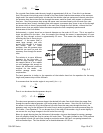
Most of the shunts used contain or can be approximated by many short capillary tubes in parallel.
From Rimberg
1
we know that the equation for the pressure drop across a capillary tube contains terms
that are proportional to the square of the volumetric flow rate. These terms come from the pressure
drops associated with the sudden compression at the entrance and the sudden expansion at the exit of
the capillary tube. The end effect terms are a function of density which will cause the quadratic term
to vary with system pressure and gas composition. The absence of viscosity in the second term will
cause a change in the relative magnitudes of the two terms whenever the viscosity of the flowing gas
changes.
()
eCa
KK
D
Q
D
LQ
++=ΔΡ
2
424
8128
π
ρ
π
μ
The end effect for a typical laminar flow element, in air, account for approximately 4% of the total
pressure drop. For hydrogen, however, which has a density that is about 14 times less than air and
has a viscosity that is much greater than air, the second term is completely negligible. For the heavier
gasses, such as sulfur hexafluoride which has a density 5 times that of air, the end effects will become
10% of the total. This fundamental property makes it a difficult to maintain accuracy specifications
when calibrating an instrument using one gas for use with another gas.
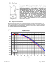
The pressure drop is linear with respect to the volumetric flow rate between a point that is
downstream of the entrance area and another point further downstream but upstream of the exit
region. From Kays & Crawford
,
that entrance length (L
) of a capillary tube in laminar flow is a
function of the Reynolds number and the tube diameter. It can be shown that:
Fig. 3.3
(3.4)
(3.3)