


300-302 Series Page 15 of 31
3. Theory of Operation
This section contains an overall functional description of the Hastings 300 series of flow instruments.
In this section and other sections throughout this manual, it is assumed that the customer is using a
Hastings power supply.
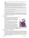
3.1. Overall Functional Description
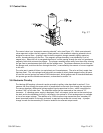
The Hastings 300 meter consists of a sensor, base, and a shunt. In addition to the components in a
meter, The 300 controller includes a control valve and extra electronic circuitry. The sensor is
configured to measure gas flow rate from 0 to 5 sccm, 0 to 10 sccm, or 0 to 20 sccm, depending on the
customer’s desired overall flow rate. The shunt divides the overall gas flow such that the flow through
the sensor is a precise percentage of the flow through the shunt. The flow through both the sensor
and shunt is laminar. The control valve adjusts the flow so that the sensor’s flow measurement
matches the set-point input. The circuit board amplifies the sensor output from the two RTD’s
(Resistive Temperature Detectors) and provides an analog output of either 0-5 VDC or 4-20 mA.
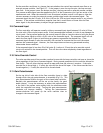
3.2. Sensor Description
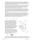
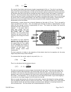
A cross section of the sensor is shown in Figure 3.1. The sensor consists of two coils of resistance wire
with a high temperature coefficient of resistance (3500 ppm/
o
C) wound around a stainless steel tube
with internal diameter of 0.6604 mm and 7.62 cm length. Each coil is 1.372 cm in length, and they are
separated by 1.27 mm distance. These two identical resistance wire coils are used to heat the gas
stream and are symmetrically located upstream and downstream on the sensor tube. Insulation
surrounds the sensor tube and heater coils with no voids around the tube to prevent any convection
losses. The ends of this sensor tube pass through an aluminum block and into the stainless steel sensor
base. This aluminum block thermally shorts the ends of the sensor tube and maintains them at
ambient temperature.
There are two coils of resistance wire that are wound around the aluminum block. The coils are
identical to each other, and are symmetrically spaced on the aluminum ambient block. These coils are
wound from the same spool of wire that is used for the sensor heater coils so they have the same
resistivity and the same temperature coefficient of resistance as the sensor heater coils. The number
of turns is controlled to have a resistance that is 10 times larger than the resistance of the heater
coils. Thermal grease fills any voids between the ambient temperature block and the sensor tube to
ensure that the ends of the sensor tube are thermally tied to the temperature of this aluminum block.
Aluminum has a very high thermal conductivity which ensures that both ends of the sensor tube and
the two coils wound around the ambient block will all be at the same temperature. This block is in
good thermal contact with the stainless steel base to ensure that the ambient block is at the same
temperature as the main instrument block and, therefore, the same temperature as the incoming gas
stream. This allows the coils wound on the aluminum block to sense the ambient gas temperature.
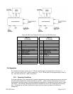
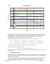
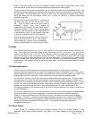
Two identical Wheatstone bridges are employed, as shown in Figure 3.2. Each bridge utilizes an
ambient temperature sensing coil and a heater coil. The heater coil and a constant value series
resistor comprise the first leg of the bridges. The second leg of each bridge contains the ambient
sensing coil and two constant value series resistors. These Wheatstone bridges keep each heater
temperature at a fixed value of
CdT °
=
48
above the ambient sensor temperature through the
application of closed loop control and the proper selection of the constant value bridge resistors.
3.3. Sensor Theory
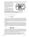
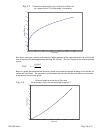
Consider the sensor design shown in Figure 3.1. The heat convected to or from a fluid is proportional
to the mass flow of that fluid.
Since the constant differential temperature sensor has 2 heater coils symmetrically spaced on the
sensor tube, it is convenient to consider the upstream and downstream heat transfer modes
separately. The electrical power supplied to either of the heater coils will be converted to heat, which