


300-302 Series Page 8 of 31
2.4. Mechanical Connections
2.4.1. Filtering
The smallest of the internal passageways in the Hastings 300 is the diameter of the sensor tube, which
is 0.026”(0.66 mm), and the annular clearance for the 500 sccm shunt which is 0.006"(0.15 mm) (all
other flow ranges have larger passages), so the instrument requires adequate filtering of the gas supply
to prevent blockage or clogging of the tube.
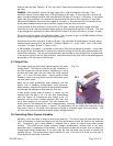
2.4.2. Mounting
There are two mounting holes (#8-32 thread) in the bottom of the transducer that can be used to
secure it to a mounting bracket, if desired.
The flow meter may be mounted in any position as long as the direction of gas flow through the
instrument follows the arrow marked on the bottom of the flow meter case label. The preferred
orientation is with the inlet and outlet fittings in a horizontal plane.
As explained in the section on operating at high pressures, pressure can have a significant affect on
readings and accuracy. When considering mounting a flow meter in anything other than a horizontal
attitude, consideration must be given to the fact that the heater coil can now set up a circulating flow
through the sensor tube, thereby throwing the zero off. This condition worsens with denser gases or
with higher pressures. Whenever possible, install the instrument horizontally.
Always re-zero the instrument with zero flow, at its normal operating temperature and purged with its
intended gas at its normal operating pressure.
2.4.3. Plumbing
The standard inlet and outlet fittings for the Hastings 300 Series are VCR-4, VCO-4 or 1/4" Swagelok. It
is suggested that all connections be checked for leaks after installation. This can be done by
pressurizing the instrument (do not exceed 500 psig unless the flow meter is specifically rated for
higher pressures) and applying a diluted soap solution to the flow connections.
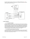
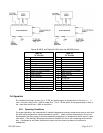
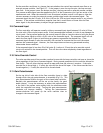
2.5. Electrical Connections
If a power supply from Hastings Instruments is used, installation consists of connecting the HFM-
300/302 series cable from the “D” connector on the rear of the power supply to the “D” connector on
the top of the flow meter /controller. The “H” pin-out requires cable AF-8-AM (grey molded
backshell). The “U” pin-out requires cable # 65-791 (black molded backshell).
If a different power supply is used, follow the instructions below when connecting the flow meter and
refer to either table 2.1 or 2.2 for the applicable pin-out. The power supply used must be bipolar and
capable of providing ±15 VDC at 55 mA for flow meter applications and ±15 VDC at 150 mA for
controllers. These voltages must be referenced to a common ground. One of the “common” pins must
be connected to the common terminal of the power supply. Case ground should be connected to the
AC ground locally. The cable shield (if available) should be connected to AC ground at the either the
power supply end, or the instrument end of the cable, not at both. Pin 6 is the output signal from the
flow meter. The standard output will be 0 to 5 VDC, where 5 VDC is 100% of the rated or full scale
flow.
The command (set point) input should be a 0-5 VDC signal (or 4-20mA if configured as such), and must
be free of spikes or other electrical noise, as these would generate false flow commands that the
controller would attempt to follow. The command signal should be referenced to signal common.
A valve override command is available to the flow controller. Connect the center pin of a single pole,
three-position switch (center off) to the override pin. Connect +15 VDC to one end of the three
position switch, and -15 VDC to the other end. The valve will be forced full open when +15 VDC is
supplied to the override pin, and full closed when -15 VDC is applied. When there is no connection to
the pin (the three-position switch is centered) the valve will be in auto control, and will obey the 0-5
VDC commands supplied to command (set-point) input.