


300-302 Series Page 24 of 31
reverse order of disassembly. A new nickel gasket will be required. Secure the endcap with 65 in lb.
(7.3 N m) to 85 in lb (9.6 N m) of torque on each stainless steel socket head cap screw. Use of a
fastener other than the one mentioned here may result in leakage at the seal. Recalibration of the
Hastings 300 is necessary.
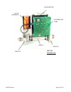
4.4. Printed Circuit Board Replacement
NOTE: This instrument contains static sensitive PC boards. Maintain static protection when handling
the PC boards.
In the event that any of the PC boards fail, they are easily removed from the instrument and replaced
with a spare. This ease in disassembly and replacement substantially reduces instrument downtime.
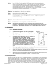
1. Replacement of the 4-20 mA option PC board: Unplug the power cable from the instruments “D”
connector. Remove the fasteners and steel can. The 4-20 mA board is the PC board mounted by
a single screw. Remove the screw and lift off the 4-20 mA board. Be careful not to damage the
main board and 4-20 mA board connectors.
2. Replacement of the main PC board: Unplug the power cable from the instruments “D”
connector. Remove the fasteners and steel can. Remove the 2 screws which fasten the main PC
board to the sensor module. Gently unplug the main board from the sensor (and from the
4-20 mA board, if present).
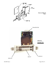
4.5. Sensor Replacement
Follow instructions for removing the PC board(s) as described in Section 4.5. Remove the 4 Allen head
cap screws that fasten the sensor to the main instrument base. Remove the sensor module from the
base, discarding the used nickel gaskets. New nickel gaskets are required for re-assembly.
To place an order or to obtain information concerning replacement parts, contact the factory
representative in your area. See the last page in this manual for the address or phone number. When
ordering, include the following information: Instrument model number, part description and Hastings
part number.