


300-302 Series Page 10 of 31
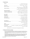
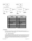
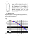
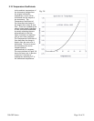
Span Error vs Pressure
(0.026" Sensor Tube)
y = 9.8877E-11x
3
3.4154E-07x -
2
8.3288E-05x +
-20.0%
-18.0%
-16.0%
-14.0%
-12.0%
-10.0%
-8.0%
-6.0%
-4.0%
-2.0%
0.0%
2.0%
0 100 200 300 400 500 600 700 800 900 1000
Pressure(psig)
Span Error (% reading)
Mean error
max
min
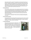
2.6.2. Zero Check
Turn the power supply on if not already energized. Allow for a 1 hour
warm-up. Stop all flow through the instrument and wait 2 minutes.
Caution: Do not assume that all metering valves completely shut off
the flow. Even a slight leakage will cause an indication on the meter
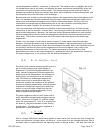
and an apparent zero shift. For the standard 0-5 VDC output, adjust
the zero potentiometer located on the inlet side of the flow meter
until the meter indicates zero (Fig 2.3). For the optional 4-20 mA
output, adjust the zero potentiometer so that the meter indicates
slightly more than 4 mA, i.e. 4.03 to 4.05 mA. This slight positive
adjustment ensures that the 4-20 mA current loop transmitter is not in
the cut-off region. The error induced by this adjustment is
approximately 0.3% of full scale. This zero should be checked
periodically during normal operation. Zero adjustment is required if
there is a change in ambient temperature, or vertical orientation of
the flow meter /controller.
2.6.3. High Pressure Operation
When operating at high pressure, the increased density of gas will cause natural convection to flow
through the sensor tube if the instrument is not mounted in a level position. This natural convection
flow will be proportional to the system pressure. This will be seen as a shift in the zero flow output
that is directly proportional to the system pressure.
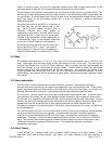
Fig. 2.4
Fig. 2.3