


300-302 Series Page 12 of 31
External Input pin (See Tables 2.1 & 2.2), the ratio of flows can be maintained over the entire range of
gas flows.
EXAMPLE: Flow controller A has 0-100 slpm range with a 5.00 volt output at full scale. Flow
controller B has 0-10 slpm range with a 5.00 volt output at full scale. If flow controller A is set at 80
slpm, its output voltage would be 4.00 volts (80 slpm/100 slpm x 5.00 volts = 4.00 volts). If the output
signal from flow controller A is connected to the command Set Point of flow controller B, then flow
controller B becomes a slave to the flow signal of controller A. The resultant flow of controller B will
be the same proportion as the ratio of the flow ranges of the two flow controllers.
If the set point of flow controller A is set at 50% of full scale, and the reference voltage from flow
controller A is 2.50, then the command signal going to flow controller B would be 2.50 volts . The flow
of gas through flow controller B is then controlled at 5 slpm (2.50 volts/5.00 volts x 10 slpm = 5 slpm).
The ratio of the two gases is 10:1 (50 slpm/5slpm). The % mixture of gas A is 90.9090 (50slpm/55 slpm
and the % mixture of gas B is 0.09091% (5 slpm/55 slpm).
Should the flow of flow controller A drop to 78 slpm, flow controller B would drop to 3.9 slpm, hence
maintaining the same ratio of the mixture. (78 slpm/100slpm x 5v = 3.90v x 50% = 1.95v; 1.95v/5.00v
x 10 slpm = 3.9 slpm; 78 slpm: 3.9 slpm = 20:1)
In the blending of two gases, it is possible to maintain a fixed ratio of one gas to another. In this case,
the output of one flow controller is used as the reference voltage for the set point potentiometer of a
second flow controller. The set point potentiometer then provides a control signal that is proportional
to the output signal of the first flow controller, and hence controls the flow rate of the second gas as a
percentage of the flow rate of the first gas.
2.7. Output Filter
The output signal may have noise superimposed on the mean
voltage levels. This noise may be due to high turbulence in
the flow stream that the fast sensor is measuring or it could
be electrical noise when the flow meter has a high internal
gain. i.e. 5 sccm full scale meter. Varying levels of radio
frequency noise or varying airflow over the electronics cover
can also induce noise.
Noise can be most pronounced when measuring the flow
output with a sampling analog/digital (A/D) converter.
When possible, program the system to take multiple samples
and average the readings to determine the flow rate.
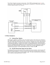
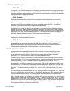
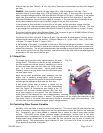
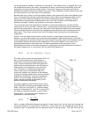
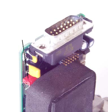
If less overall system noise is desired, a jumper may be
installed over the pins of JP-1 on the flow measurement
card. See Figure 2.6. Covering the pins closest to the “D”
connector will activate a resistor-capacitor (RC) filter that
has a time constant of one second. This will increase the
settling time of the indicated flow rate to approximately 4 seconds. Covering the other two pins will
lower the response time to approx. 1 second. This adjustment will not affect the calibration of the
flow meter circuit or the actual flow response to change in command signal (flow controllers). This
will only slow down the indicated response (output voltage/current).
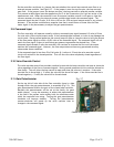
2.8. Controlling Other Process Variables
Normally, a flow controller is setup to control the mass flow. The control loop will open and close the
valve as necessary to make the output from the flow measurement match the input on the command
line. Occasionally, gas is being added or removed from a system to control some other process
variable. This could be the system pressure, oxygen concentration, vacuum level or any other
parameter which is important to the process. If this process variable has a sensor that can supply an
analog output signal proportional to its value then the flow controller may be able to control this
variable directly. This analog output signal could be 0-5 volts, 0-10 volts (or 4-20 ma for units with 4-
20 ma boards) or any value in between.
JP-1
Fig. 2.6