


300-302 Series Page 17 of 31
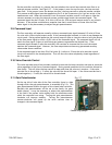
heater to the gas stream will force the upstream bridge control loop to apply more power to the
upstream heater so that the 48
o
C constant differential temperature is maintained.
The gas stream will increase in temperature due to the heat it gains from the upstream heater. This
elevated gas stream temperature causes the heat transfer at the downstream heater to gain heat from
the gas stream. The heat gained from the gas stream forces the downstream bridge control loop to
apply less power to the downstream heater coil in order to maintain a constant differential
temperature of 48
o
C.
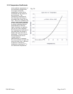
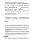
The power difference at the RTD’s is a function of
the mass flow rate and the specific heat of the
gas. Since the heat capacity of many gases is
relatively constant over wide ranges of
temperature and pressure, the flow meter may be
calibrated directly in mass units for those gases.
Changes in gas composition require application of
a multiplication factor to the nitrogen calibration
to account for the difference in heat capacity.
The sensor measures up to 20 sccm full scale flow
rate at less than 0.75% F.S. error. The pressure
drop required for a flow of 20 sccm through the
sensor is approximately 0.5 inches of H
2
O (125 Pa).
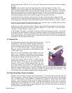
3.4. Base
The stainless steel base has a 1.5" by 1.0” (38.1 mm by 25.4 mm) cross-section and is 3.64"(92.5 mm)
long. The length from face seal fitting to face seal fitting is 4.88” (124.0 mm). The base has an
internal flow channel that is 0.75"(19.1 mm) diameter. Metal to metal seals are used between the
base and endcaps, as well as the base and sensor module. Gaskets made of nickel 200 are swaged
between mating face seals machined into the stainless steel parts. All metal seals are tested at the
factory and have leak rates of less than 1x10
-9
std. cc/s. Because of this corrosion resistant, all metal
sealed design, the Hastings 300 can measure corrosive gases, which would damage elastomer sealed
flow meters.
3.5. Shunt description
The flow rate of interest determines the size of the shunt required. As previously indicated, 9
separate shunts are required for the range of flow spanning 5 sccm to 10 slpm full scale. These shunts
employ a patented method of flow division, which results in a more linear flow meter. As a result, the
Hastings 300 flow meter calibration is more stable when changing between measured gases.
For the 5 sccm, 10 sccm, and 20 sccm flow rates a solid stainless steel shunt is used. The shunt uses a
close tolerance fit to block the main flow passage thereby directing all flow through the sensor tube.
The 50 sccm flow range uses a stainless steel shunt which has been machined flat on an edge. The gap
between the main flow passage and the flat machined on the shunt creates an alternate laminar flow
passage such that the overall gas flow is split precisely between the sensor and the shunt. By
increasing the number of flats and the size of the laminar shunt passageway, flow rates up to 200 sccm
are accommodated.
For flow rates above 200 sccm, the shunts are made so that an annular flow passage is formed between
the shunt cylinder and the main flow passage. A stainless steel plug with an annular spacing of
0.006"(0.15 mm) accommodates the 500 sccm flow range. Increased flow rates require larger gap
dimensions. Eventually, a maximum annular gap dimension for laminar flow is obtained (~0.020"(0.5
mm)). This patented shunt technology also includes inboard sensor ports which ensure laminar flow
without the turbulence associated with end effects. This unique flow geometry provides an
exceedingly linear shunt.
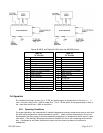
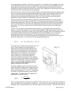
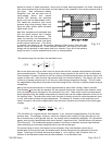
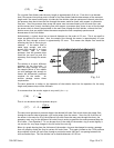
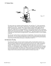
3.6. Shunt Theory
A flow divider for a thermal mass flow transducer usually consists of an inlet plenum, a flow
restriction, shunt and an outlet plenum. (See Figure 3.3) Since stability of the flow multiplier is
Fig. 3.2