


300-302 Series Page 16 of 31
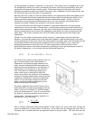
can be dissipated by radiation, conduction, or convection. The radiation term is negligible due to the
low temperatures used by the sensor, and because the sensor construction preferentially favors the
conductive and convective heat transfer modes. The thermal energy of each heater will then be
dissipated by conduction down the stainless steel sensor tube, conduction to the insulating foam, plus
the convection due to the mass flow of the sensed gas.
Because great care is taken to wind the resistive heater coils symmetrically about the midpoint of the
tube, it is assumed that the heat conducted along the sensor tube from the upstream heater will be
equal to the heat conducted through the tube from the downstream heater. Similarly, the heat
conducted from the upstream and downstream coils to the foam insulation surrounding them is
assumed to be equal, based on the symmetry of the sensor construction.
Since the sensor tube inlet and outlet are linked by an aluminum ambient bar, the high thermal
conductivity of the bar provides a ‘thermal short’, constraining the ends of the sensor tube to be at
equal surface temperature. Moreover, the tube ends and the aluminum ambient bar have intimate
thermal communication with the main flow passageway prescribed by the main stainless steel flow
meter body. This further constrains each end of the sensor tube to be equal to the ambient gas
temperature.
Further, since the length of each heater section is nearly 21 times greater than the inside tube
diameter, the mean gas temperature at the tubes axial midpoint is approximately equal to the tube
surface temperature at that point. Recall that the outside of the sensor tube is well insulated from the
surroundings; therefore the tube surface temperature at the axial midpoint is very close to the
operating temperature of the heater coils. The mean temperature of the gas stream is then
approximately the same as the heater temperature. Assuming the mean gas temperature is equal to
the heater temperature, it can be shown that the differential pressure is:
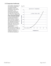
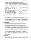
The value of the constant pressure specific heat of a
gas is virtually constant over small changes in
temperature. By maintaining both heaters at the
same, constant temperature difference above the
ambient gas stream temperature, the difference in
heater power is a function only of the mass flow
rate. Fluctuations in ambient gas temperature
which cause errors in conventional mass flow
sensors are avoided; the resistance of the ambient
sensing coil changes proportionally with the ambient
temperature fluctuations, causing the closed loop
control to vary the bridge voltage such that the
heater resistance changes proportionally to the
ambient temperature fluctuation.
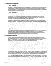
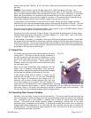
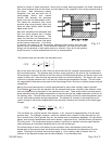
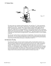
The power supplied to each of the 2 heater coils is
easily obtained by measuring the voltage across the
heater, shown as V
2
on Figure 3.2, and the voltage
across the fixed resistor R
1
. Since R
1
is in series with
the heater R
H
they have the same current flowing
through them. The electrical power supplied to a
given heater is then calculated:
()
1
221
R
VVV −
=Ρ
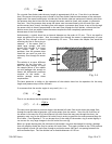
With a constant differential temperature applied to each heater coil and no mass flow through the
sensor the difference in heater power will be zero. As the mass flow rate through the sensor tube is
increased, heat is transferred from the upstream heater to the gas stream. This heat loss from the
(3.1)
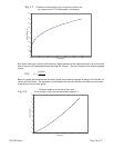
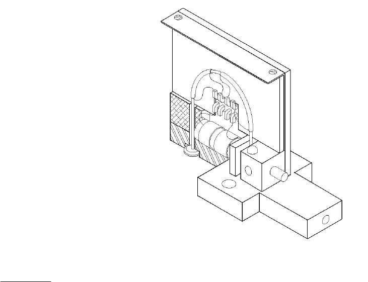
Fig. 3.1
(
3.2
)
()
ambientheaterpd
TTCmP −=−
•
2P
μ