


300-302 Series Page 19 of 31
πμ
ρ
5
Q
L
e
=
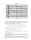
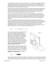
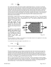
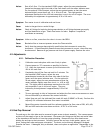
For a typical flow divider tube the entry length is approximately 0.16 cm. From this it can be seen
that if the sensor inlet pickup point is inside of the flow divider tube but downstream of the entrance
length and if the sensor outlet point is inside the flow divider tube but upstream of the exit point then
the pressure drop that drives the flow through the sensor would be linear with respect to volumetric
flow rate. Since the pressure drop across the sensor now increases linearly with the main flow rate
and the sensor has a linearly increasing flow with respect to pressure drop, there is now a flow through
the sensor which is directly proportional to the main flow through the flow divider, without the flow
division errors that are present when the sensor samples the flow completely upstream and
downstream of the flow divider.
Unfortunately, a typical shunt has an internal diameter on the order of 0.3 mm. This is too small to
insert tap points into the tube. Also, the sample flow through the sensor is approximately 10 sccm
while the flow through a shunt is approximately 25 sccm. This means the sample flow would be
affecting the flow it was trying to
measure. If the sensor tube is
made large enough, and with
enough flow through it to insert
the sensor taps at these
positions, then the pressure drop
would be too small to push the
necessary flow through the sensor
tube.
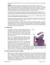
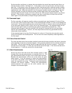
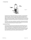
The solution is to use a different
geometry for the flow tube. It
must be large enough to allow
the sample points in the middle
yet with passages thin enough to
create the differential pressures
required for the sensor. An
annular passage meets these
requirements.
The basic operation is similar to the operation of the tubular shunt but the equations for the entry
length and pressure drop will be different.
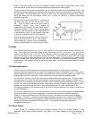
If we assume that the annular region is very small, (Δr << r):
Re
24
=
f
C
Then it can be shown that the pressure drop is:
()
3
12
τπτ
μ
Δ
=−
QL
PP
oi
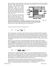
The shunt must generate a pressure drop at the desired full scale flow which drives the proper flow
through the sensor tube to generate a full scale output from the sensor. Since the full scale flow of
the sensor is the same for all of the different full scale flows that may pass through the shunt, the
geometry must vary for the different full scale flows in order to generate the same pressured drop for
all of them. From Equation 3.7 it can be seen that if the width of the annular ring is varied slightly it
can correct for very large changes in the full scale flow rate (Q).
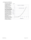
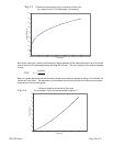
Below is a graph showing how the thickness of the annular ring must be changed to create a passage
that will properly divide the flow for various full scale flows. This graph is based on the 75 Pa pressure
drop required to push full scale flow through a particular sensor that has 2 cm spacing between the
inlet and outlet taps. The flow divider has an outside diameter of 0.95 cm.
(3.5)
Fig. 3.4
(3.6)
(3.7)