


300-302 Series Page 21 of 31
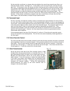
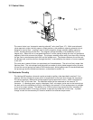
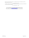
3.7. Control Valve
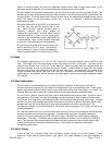
The control valve is an “automatic metering solenoid” valve (see Figure 3.7). While most solenoid
valves operate in either the fully open or closed positions, the automatic metering solenoid valve is
designed to control flow. A spring is used to hold a magnetic plunger assembly tightly against an
orifice, thereby shutting off the flow. The magnetic plunger assembly is surrounded by a coil of
magnet wire. When the coil is energized the electric current passing through the wire coil produces a
magnetic field which attracts the plunger. The plunger assembly moves away from the orifice allowing
the gas flow to pass between the orifice and the plunger seat. The distance between the orifice and
the plunger seat, and thus the flow through the valve, is controlled by the amount of current supplied
to the coil.
The valve seat is made of Kalrez (or equivalent) per fluoroelastomer. The valve orifice is made from
Stainless Steel. The valve plunger and pole piece are made of nickel plated magnetic alloy (Hi-perm
49) and the control springs are made of 302 stainless steel. Nickel gaskets seal all interfaces between
the process gas and the outside environment, as described in section 3.4.
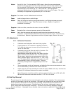
3.8. Electronic Circuitry
The Hastings 300 employs a thermal transfer principle (capillary tube described in section 3.2) to
measure the flow through the sensor which is proportional to the total flow through the instrument.
The sensor develops a differential voltage output signal proportional to flow, which is amplified to
produce 5 VDC at full scale flow. The amplified output can be measured on the external “D”
connector. If a Hastings power supply is employed, the 5 volt output is also sent to the terminals on
the back and to the decoding circuitry in the display, the optional 4-20 mA analog output is available
in lieu of an output voltage. The addition of a 4-20 mA current loop transmitter on a secondary PC
board (mounted parallel to the main pc board) is required to provide this current loop. A jumper
change is made on the secondary PC board to establish the selected output mode.
Fig. 3.7