


8
MN002000A © 2004 Navman NZ Ltd. All rights reserved. Proprietary information and specifications subject to change without notice.
2.0 Hardware interface
Details of the specific Jupiter GPS receiver’s
electrical interface are contained in the applicable
data sheet for the receiver (the latest Jupiter series
data sheets and product briefs can be downloaded
from the Navman OEM website at www.navman.
com/oem/). For information about the 2 x l0 pin
field connector, see Appendix F.
3.0 Serial data I/O interface
This section describes the formats of the two
types of messages that can be communicated
across the serial data interface for the Jupiter GPS
receivers. The structure and contents of each
binary message are described in section 3.2. The
structure and contents of each National Marine
Electronics Association (NMEA) message is
described in section 3.3.
3.1 Binary message format and word
structure
3.1.1 Binary message format
The input/output binary data stream format is a low
byte/high byte pattern. Each byte is output with
its Least Significant Bit (LSB) first, followed by its
higher order bits, ending with the Most Significant
Bit (MSB) of the data byte.
The binary message format is almost identical to
that used by the previous NavCore/MicroTracker
series of receivers, except that all floating point
values are now represented as fixed-point integer
numbers with explicit or implied scale factors.
Each binary message consists of a header
portion and a data portion, each with its own
checksum. Each message will have a header, but
some messages may not have data. Message
acknowledgements are in the form of a header,
and message requests are also made using
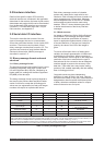
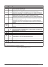
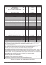
headers. Table 3-1 shows the data types used
to define the elements of the binary interface
messages.
3.1.2 Word structure
An integer is defined as 16 bits. While offsets are
incorporated in the message description tables,
the most convenient specification of memory
layout in application implementation is likely to be
a structure definition. If the item is a fixed point
quantity, the value of the LSB of the integer is
given.
To convert a fixed point item to a floating point
variable, the integer representation is floated and
multiplied by the resolution. When converting to
float, consideration must be given to the range and
resolution of the item to ensure that the type of
float selected for the conversion has an adequate
mantissa length to preserve the accuracy of the
data item. Triple word items may require scaling
portions of the variable separately and then adding
them in floating point form.
Composite words may have independent
definitions for each bit field in the word. Flag bits
are either zero (false) or one (true). All bits that are
designated as reserved within the bit descriptions
of binary data have undefined values for outputs
and must be set to zero for inputs.
Type Abbreviation Words (Note 1) Bits Maximum range
Bit (Note 2) Bit n/a 0 to 15 0 to 1
Character (Note 3)
C n/a 8 ASCII 0 to 255
Integer
I 1 16 –32 768 to +32767
Double integer DI
2 32 –2 147 483 648 to +2 147 483 647
Triple integer TI
3 48
–140 737 488 355 328 to
+ 140 737 488 355 327
Unsigned integer UI
1 16 0 to 65 535
Unsigned double integer UDI
2 32 0 to 4 294 967 295
Unsigned triple integer UTI
3 48 0 to 281 474 976 710 656
Note 1: The term ‘word’ is used throughout this document to specify a quantity which occupies 16 bits of storage.
Note 2: Data items using bit storage are specified with a format of w.b, where ‘w’ is the word number and ‘b’ is the bit number (0-15,0
LSB) within the word. Multiple-bit items (bit fields) are indicated by a range of ‘word.bit’ values (e.g. 8.4–8.7).
Note 3: Although the AAMP2 processor and C compiler use 16-bit character representations, this data interface will use the more
common 8-bit representation. The Jupiter receiver software will pack/unpack the character data internally as needed.
Table 3-1 Binary message data type