


79
MN002000A © 2004 Navman NZ Ltd. All rights reserved. Proprietary information and specifications subject to change without notice.
reserved for use by the DoD and certain authorised
users. SPS is less accurate and intended for
general public use. This is the level of accuracy
used by the Jupiter family of GPS receivers.
The SPS signal can be intentionally degraded to
a certain extent by a process known as Selective
Availability (SA). SA is used to limit access to the
full accuracy of SPS in the interest of D.S. national
security.
Differential GPS (DGPS) Description
The following general description of DGPS is from
the document RTCM Recommended Standards
For Differential NAVSTAR GPS Service. Refer to
that document for more specific details of DGPS
operations (see Appendix B).
Differential operation of the GPS offers the
possibility of accuracies from 1 m to 10 m for
dynamic, navigation applications. DGPS operation
requires a reference receiver to be placed at a
known, surveyed-in point. By comparing the known
location with that predicted by the GPS, corrections
are determined. These corrections are then
broadcast to nearby users who use them to improve
their position solutions.
Sources of bias error
The differential technique works if the main errors
are bias errors due to causes outside the receiver.
This is the case for GPS. The major sources of
error are the following:
SA errors: artificial errors introduced at the
satellites for security reasons. Pseudorange
errors of this type are about 30 m, 1-sigma.
PPS users have the capability to eliminate them
entirely.
Ionospheric delays: signal propagation group
delay, which is typically 20 to 30 m during the
day and 3 to 6 m at night.
Tropospheric delays: signal propagation
delays caused by the lower atmosphere. While
the delays are as much as 30 m at low satellite
elevation angles, they are quite consistent and
modellable. Variations in the index of refraction
can cause differences (between reference
station and user) in signal delays from 1 to 3 m
for low-lying satellites.
Ephemeris error: differences between
the actual satellite location and the location
predicted by the satellite orbital data. Normally
these are quite small, less than 3 m, but they
could be more than 30 m under SA.
Satellite clock errors: differences between
the satellite clock time and that predicted by
the satellite data. The oscillator that times the
satellite signal is free-running; the GPS ground
control station monitors it and establishes
corrections that are sent up to the satellite
to set the data message. The user reads the
data and adjusts the signal timing accordingly.
Satellite clock errors are completely
compensated by differential operation as
long as both reference and user receivers
are employing the same satellite data.
Ephemeris errors, unless they are quite large
(30 m or more) are similarly compensated by
differential operation. SA errors that affect the
timing of the signals are also compensated
by differential operation, except that the
corrections lose their validity after a period of
time.
For users near the reference station, the respective
signal paths to the satellites are sufficiently close
that compensation is almost complete. As the
separation increases between user and reference
station, the different ionospheric and tropospheric
paths to the satellites may be sufficiently far
apart that the atmospheric heterogeneities cause
the delays to vary. The extent of the difference
constitutes an error in the DGPS measurement,
called ‘spatial decorrelation’. This type of error
will be greater at larger ‘user-to-reference station’
separations.
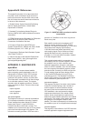
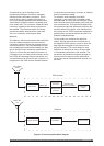
Required DGPS Equipment
The equipment consists of a GPS receiver with
antenna, a data processor, a data link receiver with
antenna, and interfacing equipment as illustrated
in Figure C-5. The data processor applies the
corrections received from the reference station to
the pseudoranges measured by the sensor.
Application of DGPS Corrections
For each satellite employed by the user’s receiver,
the correction obtained from the reference
station (message type 1 or 9) is added to the
pseudorange measurement. The correction itself is
derived from the range and range-rate, adjusted to
account for the time elapsed between the time of
reception of the correction and the time of the user
pseudo-range measurement, as follows:
PRC(t) = PRC(t
0
) + RRC x [t-t
0
]
where:
PRC(t) is the correction to be applied
PRC(t
0
) is the range correction from the
message RRC is the range-rate correction
from the message
(t
0
) is the time reference of the correction
(t) is the time associated with the pseudo-
range measurement.