


22
MN002000A © 2004 Navman NZ Ltd. All rights reserved. Proprietary information and specifications subject to change without notice.
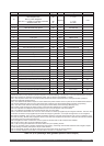
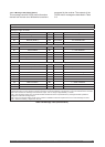
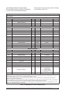
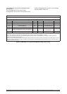
Message ID: 1012
Rate: variable
Message length: 22 words
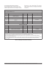
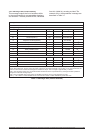
Word No. Name Type Units Range Resolution
1-4 Message header
5 Header checksum
6-7 Set time (Note 1) UDI 10 ms ticks 0 to 2 147 483 647
8 Sequence number (Note 2) I 0 to 32 767
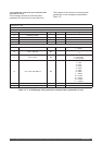
Operational status (9.0-9.15)
9.0 Power management enabled Bit 1 = enabled
9.1 Cold start disabled Bit 1 = disabled
9.2 DGPS disabled Bit 1 = disabled
9.3 Held altitude disabled Bit 1 = disabled
9.4 Ground track smoothing disabled Bit 1 = disabled
9.5 Position pinning disabled Bit 1 = disabled
9.6 Quality measurement disabled (Note 3) Bit 1 = disabled
9.7 Jamming detection enabled Bit 1 = enabled
9.8 Active antenna Bit 1 = active, 0 = passive
9.9-9.15 C/No threshold dBHz 0 to 50
10 Cold start time-out UI
s 0 to 32 767
11 DGPS correction time-out UI
s 0 to 32 767
12 Elevation mask
I rad 0 to ±�/2 10
-3
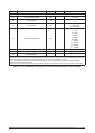
Selected candidates
13.0-14.15 Selected candidate (Note 4) Bit 1 = included candidate
Solution validity criteria (15-20)
15.0 Attitude not used Bit 1 = required
15.1 Differential GPS Bit 1 = required
15.2 DR measurement Bit 1 = required
15.3 GPS calibration Bit 1 = required
15.4 GPS only Bit 1 = required
155-15.15 Reserved
16 Number of satellites in track required UI 0 to 12
17-18 Minimum expected horizontal error UDI
m 0 to 1000 10
-2
19-20 Minimum expected vertical error UDI m 0 to 1000 10
-2
21 Application platform UI
0 = default, 1 = static
2 = pedestrian
3 = marine (lakes)
4 = marine (sea level)
5 = land (auto), 6 = air
22 Data checksum
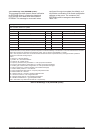
Note 1: Set time is an internal 10 ms (T10) count since power-on initialisation enabled the processor interrupts. It is not used to
derive GPS time, but provides sequence of events knowledge. The T10 count references the receiver’s internal time at which the
message was created for output. The T10 range is approximately 71 weeks.
Note 2: The sequence number is a count that indicates whether the data in a particular binary message has been updated or
changed since the last message output.
Note 3: If this bit is set, the receiver only uses ‘perfect’ measurements (i.e. without errors in tracking status or data). If the bit is not
set, measurements that are not perfect, but still good enough to use under SPS conditions, are used.
Note 4: The selected candidate list is a 32-bit flag, each bit representing candidate selection status for one satellite (ie bit 0 = SV1
status, bit 1 = SV2 status, bit 31 = SV32 status).
Table 3-12 Message 1012 (user-settings output)
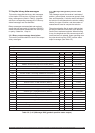
3.5.1.8 Message 1012 (user settings output)
This message provides a summary of the settings
for many of the user-definable parameters.
The contents of the ‘user settings output’ message
are described in Table 3-12.