


40
MN002000A © 2004 Navman NZ Ltd. All rights reserved. Proprietary information and specifications subject to change without notice.
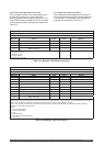
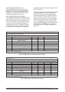
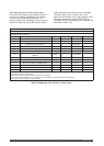
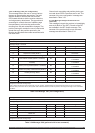
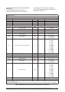
Message ID: 1221
Rate: as required (maximum rate is 1 Hz)
Message length: 15 words
Word No. Name Type Units Range
1-4 Message header
5 Header checksum
6 Sequence number (Note 1) I 0 to 32 767
Nav configuration word (7.0-7.15)
7.0 Held altitude disable (default = enabled) Bit
0 = enabled
1 = disabled
7.1
Ground track smoothing disable (default =
enabled)
Bit
0 = enabled
1 = disabled
7.2 Position pinning disable (default = enabled) Bit
0 = enabled
1 = disabled
7.3 Disable low quality measurements (Note 2) Bit
0 = enabled
1 = disabled
7.4 Enable jamming detect Bit
0 = enabled
1 = disabled
7.5-7.15 Reserved (must be zeroed out) Bit
0
8-14 Reserved (must be zeroed out)
15 Data checksum
Note 1: The sequence number is a count that indicates whether the data in a particular binary message has been updated or
changed since the last message input.
Note 2: When this bit is set, the receiver will only use “perfect” measurements (ie measurements without any errors in tracking
status or data). If the bit is not set, the system uses measurements that, while not perfect, are still good enough to use under SPS
conditions.
Table 3-33 Message 1221 (nav configuration)
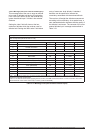
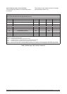
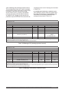
Message ID: 1300
Rate: as required (maximum rate approximately 0.1 Hz)
Message length: 8 words
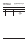
Word No. Name Type Units Range
1-4 Message header
5 Header checksum
6 Sequence number (Note 1) I 0 to 32 767
7 Reserved
8 Data checksum
Note 1: The sequence number is a count that indicates whether the data in a particular binary message has been updated or
changed since the last message input.
Table 3-34 Message 1300 (perform built-in test command)
3.5.2.11 Message 1221 (nav configuration).
This message allows the user to control various
features in the navigation processing. The held
altitude disable bit controls the use of stored
GPS-based altitude to aid the receiver when the
vertical geometry deteriorates. The ground track
smoothing bit controls the use of satellite range
bias estimates to minimise the position shifts
resulting from SA and constellation changes. The
position pinning bit controls the use of a horizontal
speed test to pin the position reported by the
receiver and eliminate the wander associated with
SA when static.
Ground track smoothing and position pinning are
not used when DGPS corrections are in use. The
contents of the ‘nav configuration’ message are
described in Table 3-33.
3.5.2.12 Message 1300 (perform built-in test
command).
This message instructs the receiver to immediately
execute its Built-In Test (BIT). Results of the BIT
are available in the BIT results message. The
contents of the ‘perform built-in test command’
message are described in Table 3-34.