


7
MN002000A © 2004 Navman NZ Ltd. All rights reserved. Proprietary information and specifications subject to change without notice.
pre-amplifier
(optional)
Jupiter
GPS receiver
power
supply
DGPS
(optional)
OEM
application
processor
display
keypad
power/communications interface
GPS antenna
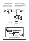
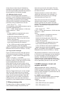
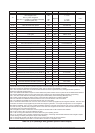
2. The Scorpio device, which contains an
integral microprocessor and all GPS specific
signal processing hardware.
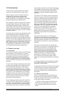
In addition, memory and other supporting
components configure the receiver into a complete
navigation system. Figure 1-3 illustrates an
architecture that might be used to integrate a
particular Jupiter receiver with an application
processor that drives peripheral devices such as a
display and keyboard. The interface between the
application’s processor and the Jupiter receiver is
through the serial data interface.
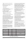
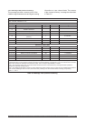
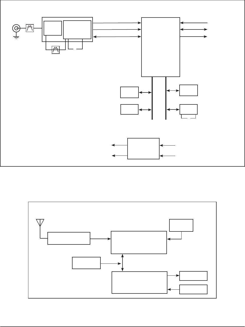
Figure 1-2 Internal Jupiter architecture
Figure 1-3 Possible Jupiter/OEM architecture
LNA
down
converter
12 channel
GPS
correlator
SRAM
serial
EEPROM
ROM*
RTC
EMI filtering
& power supply
0
0
*contains
software
ADD
BUS
12C
BUS
regulated DC power
bat. backup to SRAM & RTC
+3.3 or 5.0 VDC input
+3.3 or 5.0 VDC
bat. backup
RF
connector
pre-select
filter
post-select
filter
10.949 MHz
Xtal
32 kHz Xtal
serial port 2
serial port 1
1PPS, 10 kHz
signal samples
clock signals
A/D control
CX74051
receiver front-end
CX11577
baseband processor
timing reference
OEM host interface
GDGPS data
(RTCMSC-104)