


25
MN002000A © 2004 Navman NZ Ltd. All rights reserved. Proprietary information and specifications subject to change without notice.
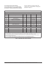
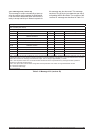
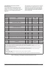
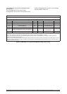
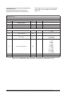
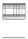
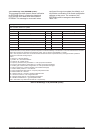
Message ID: 1110
Rate: variable
Message length: 22 words
Word No. Name Type Units Range Resolution
1-4 Message header
5 Header checksum
6-7 Set time (Note 1) UDI 10 ms ticks 0 to 4 294 967 295
8 Sequence number (Note 2) I 0 to 32 767
9 Frequency standard issue number (Note 3) UI 0 to 65 535
Temperature characteristic
10 C0 (aging and calibration offset) (Note 4)
I s/s 0 to ±2
-14
2
-29
11 C1 (linear term) (Note 4) I s/s/ºC 0 to ±2
-20
2
-35
12 C2 (second order term) (Note 4) I s/s/(ºC)
2
0 to ±2
-26
2
-41
13 C3 (third order term) (Note 4) I s/s/ºC)
3
0 to ±2
-32
2
-47
14 TINF (inflection point) (Note 4) I ºC 0 to ±100 0.01
Temperature dynamics
15 D0 (Note 5)
I
16 D1 (Note 5)
I
Temperature sensor calibration
17 TREF (calibration reference temperature) (Note 6)
I ºC 0 to ±100 0.01
18 T0 (temperature sensor reading at TREF) (Note 6) UI counts 0 to 65 535
1
19 S0 (temperature sensor scale factor) (Note 6)
I ºC/count 0 to ±2
-3
2
-18
Uncertainty coefficients
20 U0 (Note 7)
I s/s 0 to ±2
–14
2
-29
21 U1 (Note 7) I s/s/ºC 0 to ±t2
–20
2
-35
22 Data checksum
Note 1: Set time is an internal 10 millisecond (T10) count since power-on initialisation enabled the processor interrupts. It is not used
to derive GPS time, but only serves to provide a sequence of events knowledge. The set time or T10 count references the receiver’s
internal time at which the message was created for output. The T10 range is approximately 71 weeks.
Note 2: The sequence number is a count that indicates whether the data in a particular binary message has been updated or
changed since the last message output.
Note 3: Unique identification of each update. This allows a different set of data to be in use while newer data are only stored to
EEPROM. The issue number is preserved from run to run if non-volatile storage is available.
Note 4: Defines a cubic in (T - TINF). Over a range of TINF+65 degrees C, each term can produce from 0.002 to 60 ppm,
approximately.
Note 5: Unused.
Note 6: These parameters define the temperature sensor scaling according to the equation:
T = TREF + (TFILT- T0)S0
Note 7: Defines a linear equation in (T - TINF). Over a range of TINF +65ºC, each term can produce from 0.002 to 60 ppm,
approximately.
Table 3-15 Message 1110 (frequency standard parameters in use)
3.5.1.11 Message 1110 (frequency standard
parameters in use)
This message outputs the parameters used to
support the receiver’s uncompensated crystal
oscillator. The contents of the ‘frequency standard
parameters in use’ message are described in
Table 3-15.
Note: Message 1110 is primarily used to output key
parameters to GPS systems without non- volatile
storage. This is why the format of input Message
1310 is exactly the same—the output message is
used to capture data, while the input message is
used to restore data.