


4G1 ENGINE (E-W) -
Crankshaft and Cylinder Block
11A-12-2
PWEE9520
E
Nov. 1995Mitsubishi Motors Corporation
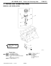
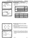
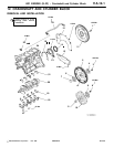
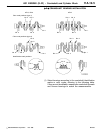
Removal steps
1. Flywheel bolt
2. Flywheel
3. Flywheel bolt
4. Adapter plate
5. Flywheel
6. Adapter plate
7. Crankshaft bushing
8. Drive plate bolt
9. Adapter plate
10. Drive plate
11. Crankshaft bushing
12. Rear plate
13. Bell housing cover
"
D
A
14. Rear oil seal
15. Rear oil seal case
16. Rear oil seal case gasket
"
C
A
17. Bearing cap bolt
"
C
A
18. Bearing cap
"
B
A
19. Crankshaft bearing (lower)
20. Crankshaft
"
B
A
21. Crankshaft bearing (upper)
A
A
""
A
A
22. Oil pressure switch
23. Knock sensor
<4G13, SOHC 16-VALVE>
24. Cylinder block
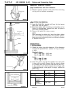
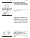
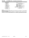
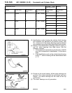
Caution
On the flexible flywheel equipped engines, do not remove any of the bolts “A” of the flywheel
shown in the illustration.
The balance of the flexible flywheel is adjusted in an assembled condition. Removing the bolt,
therefore, can cause the flexible flywheel to be out of balance, giving damage to the flywheel.
PWEE9520-A
E
Dec. 1998Mitsubishi Motors Corporation Revised