


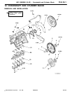
4G1 ENGINE (E-W) -
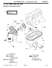
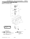
Pistons and Connecting Rods
11A-11-5
PWEE9520
E
Nov. 1995Mitsubishi Motors Corporation
"
C
A
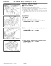
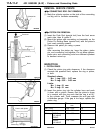
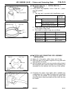
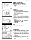
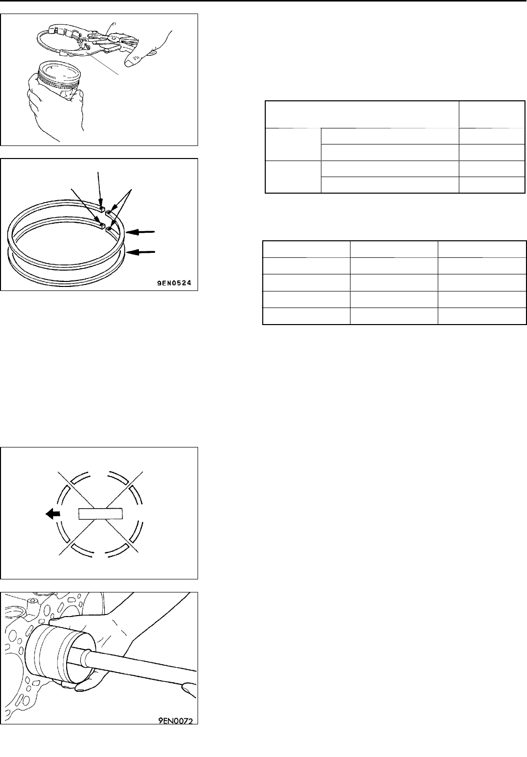
PISTON RING No. 2 / PISTON RING No. 1
INSTALLATION
(1) Using piston ring expander, fit No. 2 and No. 1 piston
ring into position.
NOTE
1. The ring end is provided with identification mark.
Item Identifica-
tion mark
No. 1 ring With catalytic converter 1T
Without catalytic converter T
No. 2 ring With catalytic converter 2T
Without catalytic converter T2
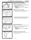
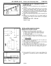
2. Install piston rings with identification mark facing up,
to the piston crown side.
3. Size marks on piston rings are as follows.
Size Size mark
STD None ALL
0.25 mm O. S. 25 4G18
0.50 mm O. S. 50 ALL
1.00 mm O. S. 100 4G13, 4G15
"
D
A
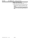
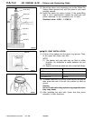
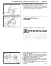
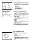
PISTON AND CONNECTING ROD ASSEMBLY
INSTALLATION
(1) Apply oil to the piston, piston rings, and oil ring.
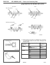
(2) Align the gaps of the piston rings an d oil ring (side rails
and spacer) as shown.
(3) With the piston crown’s front arrow mark pointing toward
the timing belt side, press t he piston and connecting rod
assembly into the cylinder from the top of the cylinder.
(4) Compress the piston rings tightly with a suitable ring
compression tool, then press the piston and connecting
rod fully into the cylinder. Do not strike the piston hard
since th e piston rings may break and the crank pin may
be nicked.
PWEE9520-A
E
Dec. 1998Mitsubishi Motors Corporation Revised
Piston ring expander
7EN0452
Identification mark
Identification mark
Size mark
No. 1
No. 2
Side rail
No. 2 ring and
spacer
Side rail
Piston pin
No. 1 ring
6EN0549