


4G1 ENGINE (E-W) -
Pistons and Connecting Rods
11A-11-7
PWEE9520
E
Nov. 1995Mitsubishi Motors Corporation
"
F
A
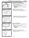
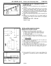
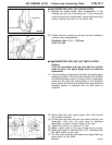
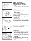
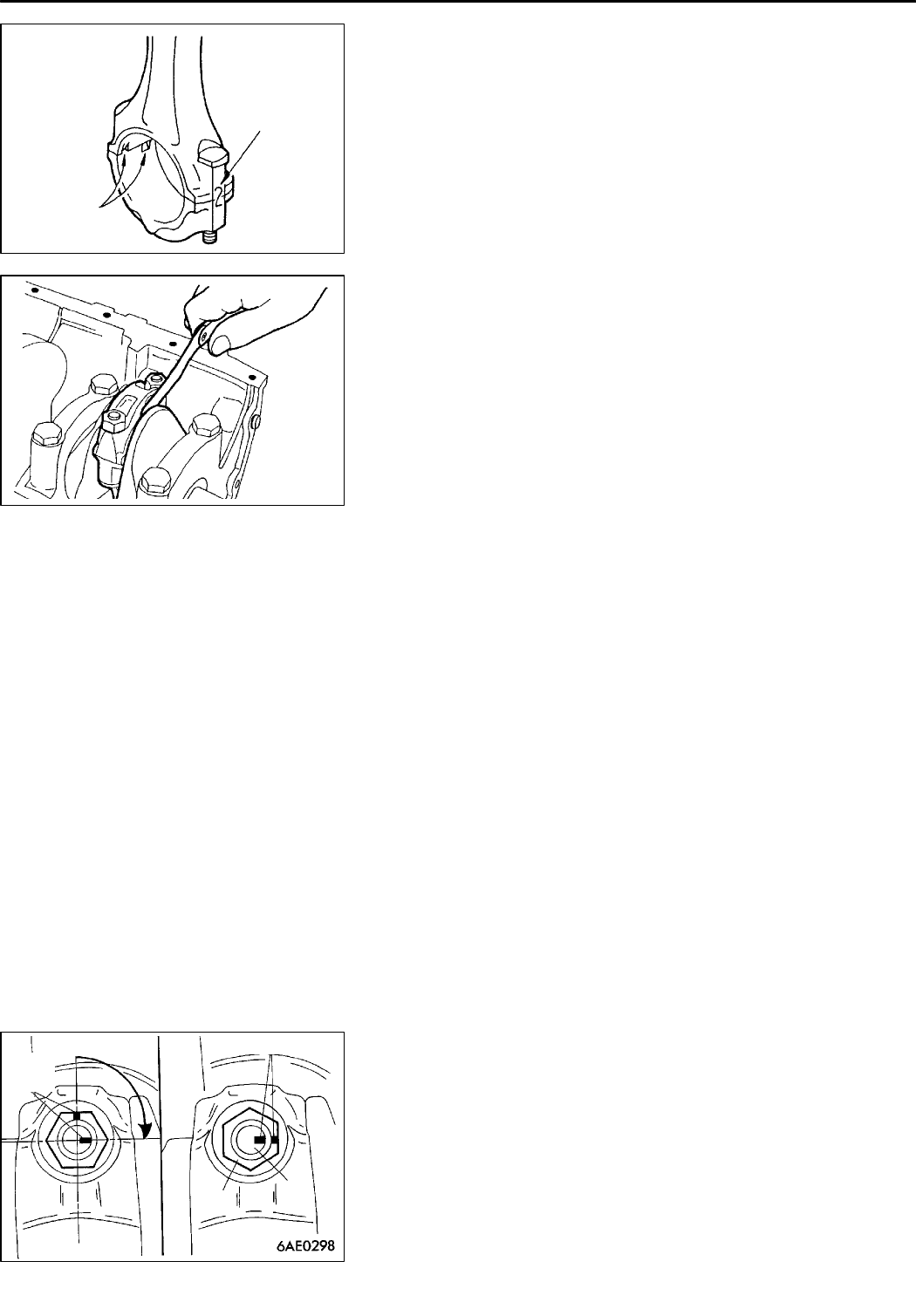
CONNECTING ROD CAP INSTALLATION
(1) Aligning t he marks made during disassembly, fit the
bearing cap onto the connecting rod. If the connecting
rod is new and has no index mark, ensure that the bearing
locking notches are both on the same side.
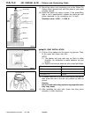
(2) Check that the connecting rod big en d side clearance
confirms with specifications.
Standard value: 0.10 - 0.25 mm
Limit: 0.4 mm
"
G
A
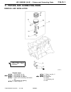
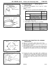
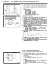
CONNECTING ROD CAP NUT INSTALLATION
Caution
To fit the connecting rod cap nuts with the cylinder
head in place, the spark plugs must be removed
beforehand.
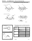
(1) The connecting rod bolts and nuts utilize the plastic region
tightening method. The bolts must therefore be checked
for stretching before reuse. To check a bolt for stretching,
screw the nut down the entire length of the thread by
hand. Unless the nut turns smoothly all the way, the bolt’s
threaded section is stretched and the bolt must be
replaced.
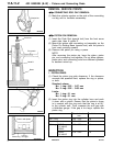
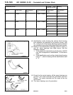
(2) Before fitting the nuts, apply engine oil to their threads
and seating surfaces.
(3) Fit the nuts onto the bolts and turn them until they are
finger-tight. After this, the nuts must be tightened
alternately to ensure correct fitting of the cap.
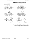
(4) Tighten the nuts to a torque of 17 Nm.
(5) Make a paint mark on the top of each nut as shown.
(6) Make paint marks on the bolts 90 to 100
_
clockwise from
the paint marks on the nuts.
(7) Turn the nuts until their paint marks are aligned with the
paint marks on the bolts.
PWEE9520-A
E
Dec. 1998Mitsubishi Motors Corporation Revised
Cylinder No.
DEN0051
Locking notch
1EN0276
90
_
- 100
_
Paint
mark
Paint mark
Nut
Bolt