


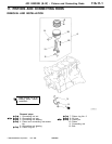
4G1 ENGINE (E-W) -
Pistons and Connecting Rods
11A-11-2
PWEE9520
E
Nov. 1995Mitsubishi Motors Corporation
REMOVAL SERVICE POINTS
A
A
"
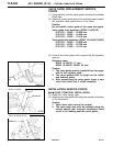
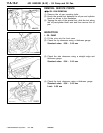
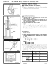
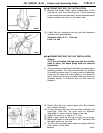
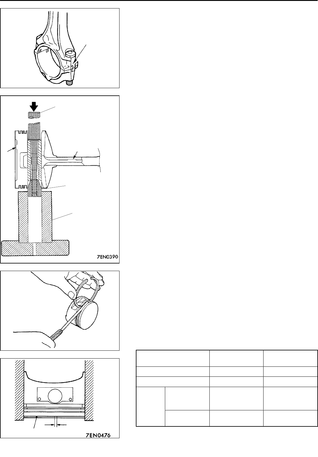
CONNECTING ROD CAP REMOVAL
(1) Mark th e cylinder number on the side of the connecting
rod big end to facilitate reassembly.
A
B
"
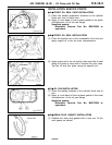
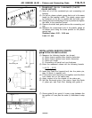
PISTON PIN REMOVAL
(1) Insert the Push Rod (special tool) from the front arrow
mark side, then fit guide D.
(2) Mount the piston a n d connecting rod assembly on the
Piston Pin Setting Base (special tool) with the piston’s
front mark pointing upward.
(3) Remove the piston pin using a press.
NOTE
After removing the piston pin, keep the piston, piston
pin, and connecting rod together. Do not allow pistons,
piston pins, and connecting rods from different cylinders
to become mixed up.
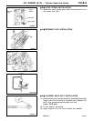
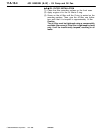
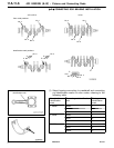
INSPECTION
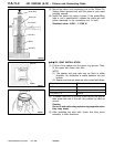
1. PISTON RINGS
(1) Check the piston ring side clearance. If the clearance
exceeds th e specified limit, replace t h e ring or piston,
or both.
Standard values:
No. 1 ring: 0.03 - 0.07 mm
No. 2 ring: 0.02 - 0.06 mm
Limits:
No. 1 ring: 0.1 mm
No. 2 ring: 0.1 mm
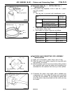
(2) Insert the piston ring into the cylinder bore and push
it down with a piston. Ensure that the piston’s crown
is in contact with the ring such that the ring is at 90
_
to the cylinder wall. Then, measure the en d gap with
a thickness gauge. If the gap is too large, replace the
piston ring.
Standard values
mm
Limits mm
No. 1 ring 0.20 - 0.35 0.8
No. 2 ring 0.35 - 0.50 0.8
Oil ring SOHC
12-VALVE,
DOHC
0.20 - 0.50 1.0
SOHC
16-VALVE
0.10 - 0.40 1.0
PWEE9520-A
E
Dec. 1998Mitsubishi Motors Corporation Revised
Cylinder No.
DEN0050
Push rod
Front
mark
Front mark
Guide D
Base
7EN0475
Push in with piston
Piston ring
End gap