


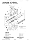
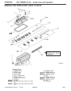

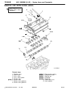
4G1 ENGINE (E-W) -
Rocker Arms and Camshafts
11A-8-7
PWEE9520
E
Nov. 1995Mitsubishi Motors Corporation
"
B
A
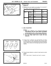
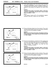
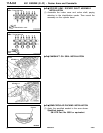
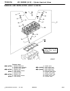
BEARING CAP INSTALLATION
(1) Position t h e camshaft dowel pins as shown.
NOTE
With the camshaft dowel pins in this position, t he camshaft
notches for tightening cylinder head bolt are correctly
positioned.
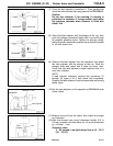
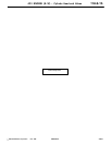
(2) Bearing caps Nos. 2 to 5 are the same shape. Be sure
to install them in order of their cap numbers and check
the identification marks to ensure that the intake and
exhaust sides are not reversed.
Identification marks:
I: Intake
E: Exhaust
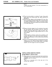
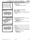
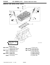
(3) Apply the specified sealant to the surfaces that are to
mate with the cylinder head. Then, tighten the bearing
cap bolts - for the middle caps first, then for the outer
caps, and soon. Tighten the bolts a little at a time such
that each bolt is tightened to the specified torque in the
final sequence.
Specified sealant:
3M ATD Part No. 8660 or equivalent
(4) Check that the rocker arms are installed correctly.
"
C
A
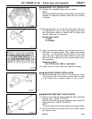
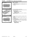
ADJUSTING SCREW INSTALLATION
(1) Install provisionally th e screw to the rocker arm. Insert
it so that the end of the screw is flush with the edge
of the rocker arm or projects slightly (1 mm or less).
"
D
A
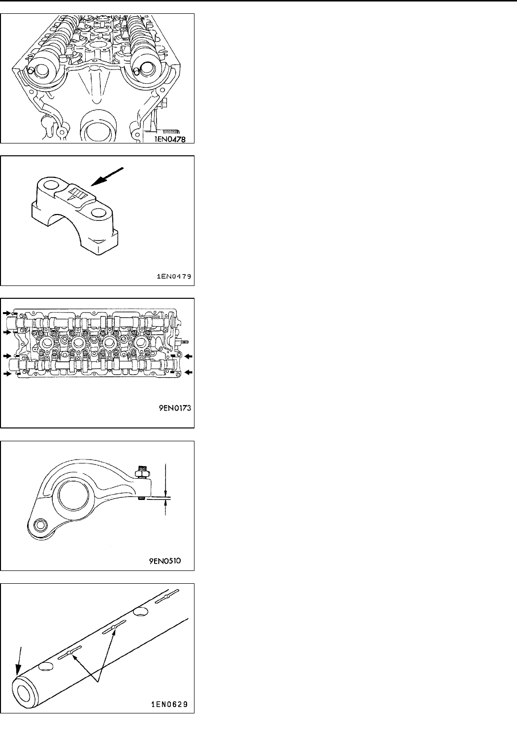
ROCKER ARM SHAFT INSTALLATION
(1) Place the end with the larger chamfered side toward the
flywheel side. <SOHC 12-VALVE>
Place the end with the larger chamfered side toward the
timing belt side. <SOHC 16-VALVE>
NOTE
The rocker arm shaft for intake valves have eight oil holes.
(2) Place the section of the shaft with the oil holes toward
the cylinder head.
PWEE9520-A
E
Dec. 1998Mitsubishi Motors Corporation Added
1 mm or less
Chamfer
Oil holes