


4G1 ENGINE (E-W) -
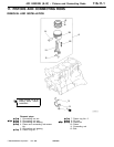
Pistons and Connecting Rods
(A-C) - (B-D)
L=
2
11A-11-3
PWEE9520
E
Nov. 1995Mitsubishi Motors Corporation
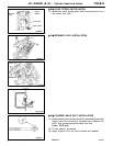
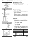
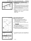
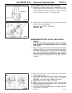
2. CRANKSHAFT PIN OIL CLEARANCE (PLASTIC
GAUGE METHOD)
(1) Wipe all oil off the crankshaft pin and connecting rod
bearing.
(2) On the pin, place a plastic gauge that is cut to the same
length as the bearing’s width. The plastic gauge must
be centered on th e pin in parallel with the pin’s axis.
(3) Gently place the connecting rod cap in position and tighten
the bolts to the specified torque.
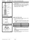
(4) Remove the bolts an d gently remove the connecting rod
cap.
(5) Measure the compressed part of the plastic gauge at
its widest point using the scale printed on the plastic
gauge bag.
Standard value: 0.02 - 0.04 mm
Limit: 0.1 mm
INSTALLATION SERVICE POINTS
"
A
A
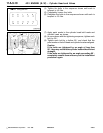
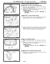
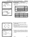
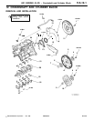
PISTON PIN INSTALLATION
(1) Measure the following lengths (as shown):
A: Piston boss-to-piston boss outside dimension
B: Piston boss-to-piston boss inside dimension
C: Piston pin length
D: Connecting rod small end eye thickness
(2) Enter the measured values into the following formula:
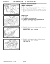
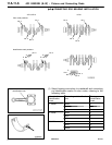
(3) Insert the Push Rod (special tool) into the piston pin,
then fit Guide A (special tool).
(4) Fit the piston and connecting rod together such that their
front marks are on the same side.
(5) Apply engine oil to the outside of the piston pin.
(6) Into the front-mark side of the piston, insert the Guide
A, piston pin, and Push Rod, starting with guide A.
(7) Screw guide B into guide A. Leave a gap between the
two guides of 3 mm plus the value (L) calculated in step
(2).
Connecting rod
Piston
Piston pin
D
BA
C
Guide B
Guide A
3mm
+
L