4D68 ENGINE (E- W) -
Crankshaft, Cylinder Block and Flywheel
11A-12-7
INSPECTION
(1) After removing the cylinder sleeve,check the cylinder block
sleeve hole surface.
If there is damage, insufficient interference-fit-margin or
other problems, bore the cylinder block sleeve hole to
an oversize.
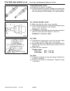
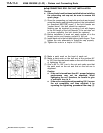
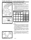
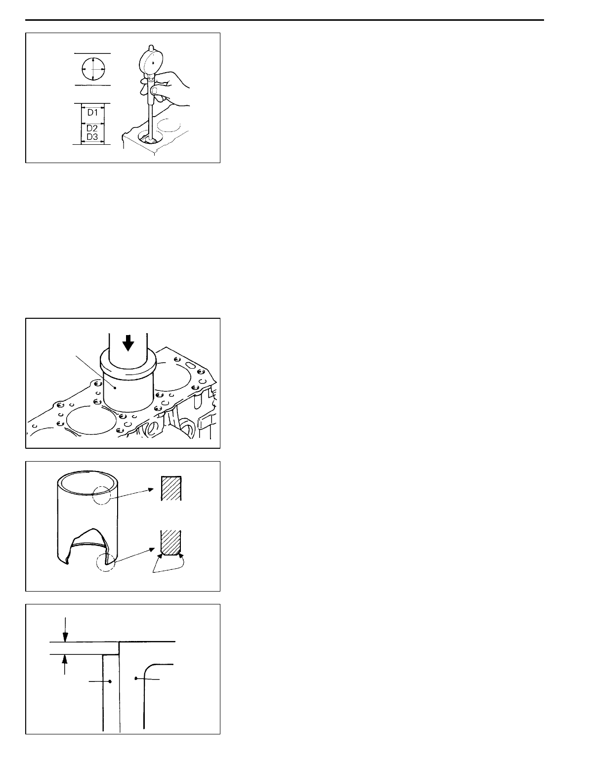
(2) To checkthe interference,measure boththecylindersleeve
O.D. an d cylinder block sleeve hole I.D. at the positions
D
1
,D
2
and D
3
in both X and Y directions.
(3) If the average of the differences between measured values
is smaller than 0.12 mm, then bore the sleeve hole to
0.5 mm oversize and install an oversize sleeve. If the
average is larger than 0.175 mm, bore the sleeve hole
to the extent that the difference falls within a range of
0.12 to 0.175 mm, then install a standard cylinder sleeve.
Caution
D
If one cylinder requires oversize machining,
oversize itwiththe othercylinder sleevesremoved.
Machining while the sleeves remain in the other
cylinders may disturb roundness.
INSTALLATION
When cylinder block sleeve hole has not been bored
(1) Amply apply press oil to the cylinder block sleeve hole
and sleeve outer circumference.
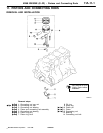
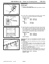
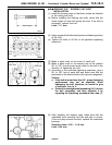
(2) Apply a disc [diameter 100 mm, thickness 20 mm or more]
to the top of the sleeve and press fit using a hydraulic
press.
Installation load: 22,000 N or more
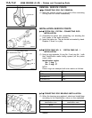
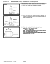
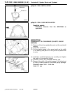
(3) Install with the chamfered end first as illustrated. Continue
until the sleeve upper end is flush with the block upper
end.
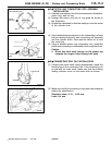
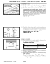
(4) Cut off the t op end of the cylinder block in order to make
the cylinder blockflush with the sleeve.Cut off the minimum
top end portion of the cylinder block necessary to make
them flush. Do not cut off more than 0.2 mm.
PWEE9609
E
Dec. 1996Mitsubishi Motors Corporation
DEN116
12 mm
Lower
Center
X direction
Y direction
DEN241
Hydraulic press
Cylinder sleeve
DEN242
Chamfered
Top end
Bottom end
DEN243
Cylinder
sleeve
Cylinder
block
To be flush


